Software Download
Betaflight (BF flight controller tuning software)
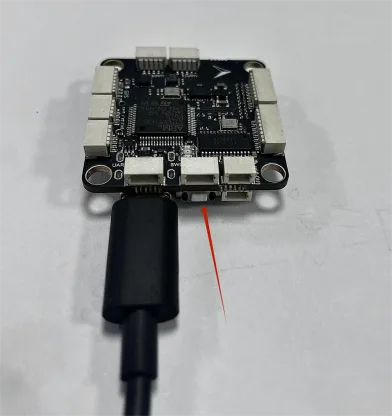
Prepare a USB-A to USB-C data cable for connecting the computer to the flight controller. When firmware flashing is required, hold the BOOT button on the flight controller first, then plug in the USB cable.
Web flashing link: https://flasher.corvon.tech/
One-Click Firmware Flashing
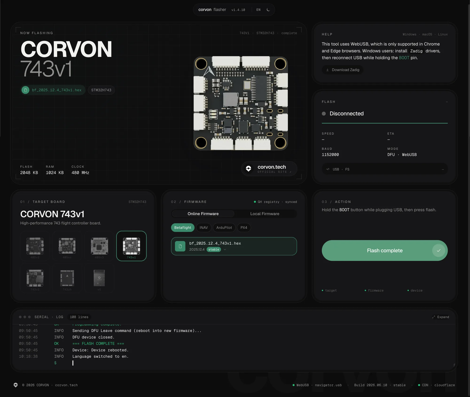
Copy the CORVON web flasher link and open it in Chrome or another browser that supports WebUSB.
https://flasher.corvon.tech/
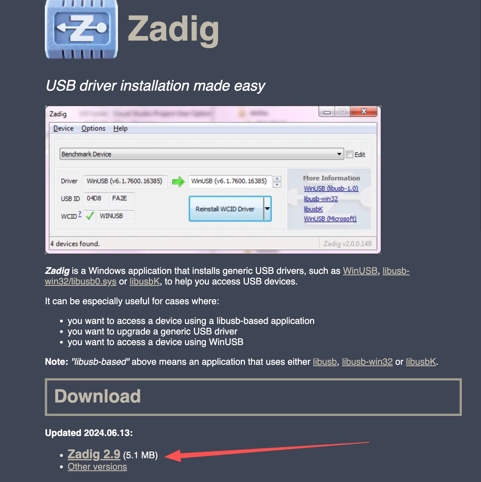
Install Zadig before flashing. Zadig is used to install the DFU driver for the flight controller. Refer to the image below for the download location.
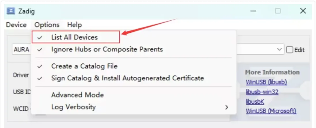
Open the Zadig download entry in the upper-right corner of the page. After running Zadig, enable List All Devices in the Options menu.
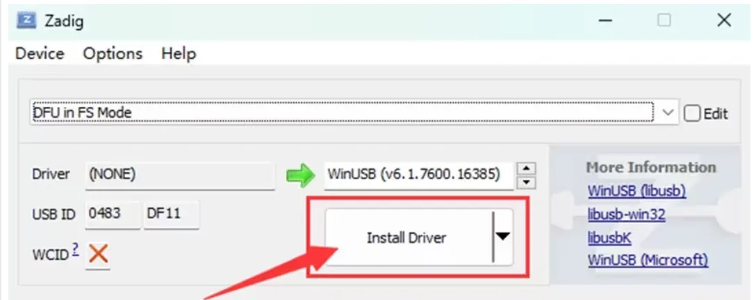
Open the device list and select DFU in FS Mode. If the flight controller MCU is STM32F405, the device name may appear as STM32 BOOTLOADER. If the device cannot be found in the list, make sure the BOOT button was held before plugging in USB, and check that the USB cable supports data transfer.

Click Install Driver to install the WinUSB driver. Wait a few minutes, then open Windows Device Manager after the driver installation is complete.
If DFU in FS Mode is visible, the computer has correctly recognized the flight controller in DFU mode.
After the flight controller enters DFU mode, follow the steps below to flash the firmware.
Prepare the CORVON flight controller and a USB-A to USB-C data cable.
Open the online flashing page. Hold the BOOT button next to the flight controller USB port first, then plug in the USB cable to connect it to the computer. Release the button about 2 seconds after the flight controller powers on. Then select the target flight controller and Betaflight firmware in sequence, click Flash, choose the recognized DFU device in the pop-up device selection window, and wait for flashing to complete.
The firmware on the online flashing page is continuously updated. Use the version displayed on the page as the reference.
Betaflight Basic Tuning
Connect the flight controller: use a USB cable to connect the flight controller to the computer, then open the Betaflight web configurator: https://app.betaflight.com/#.

Select the device and connect: choose the corresponding serial port from the I can't find my USB device drop-down list. After Betaflight STM Electronics is detected, click Connect to enter the configuration interface.
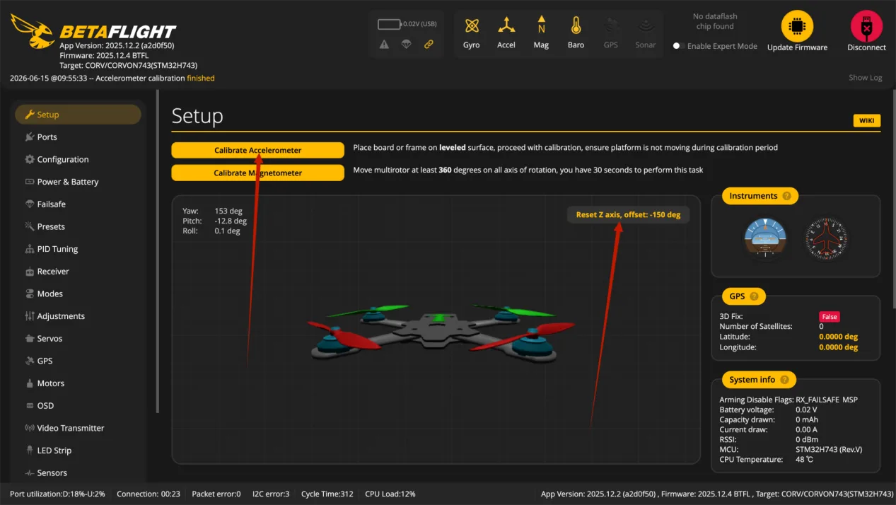
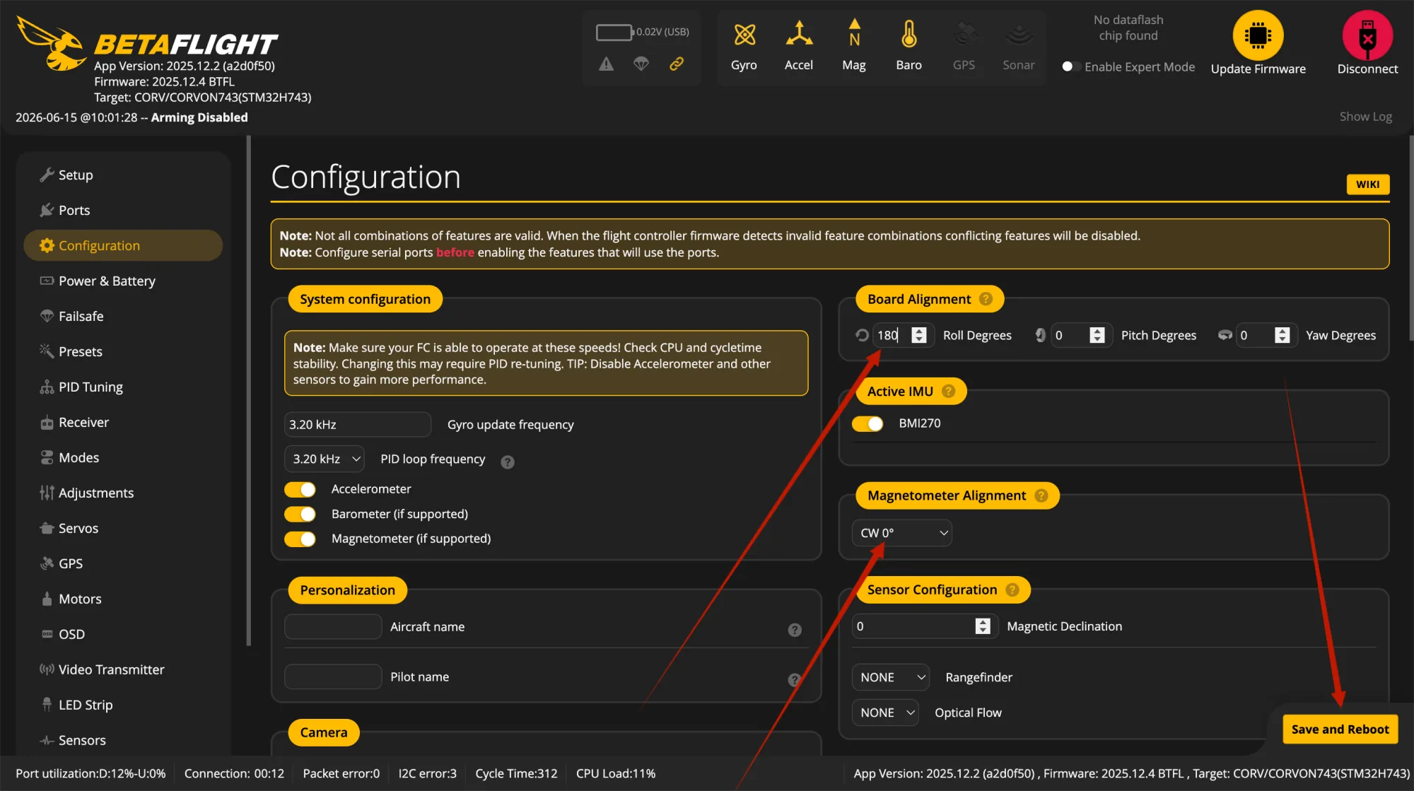
Calibrate attitude: enter the Setup page, place the flight controller level on a stable desk, and click Calibrate Accelerometer. The model attitude in the software should match the real airframe. If the direction is incorrect, check Board Alignment on the Configuration page.
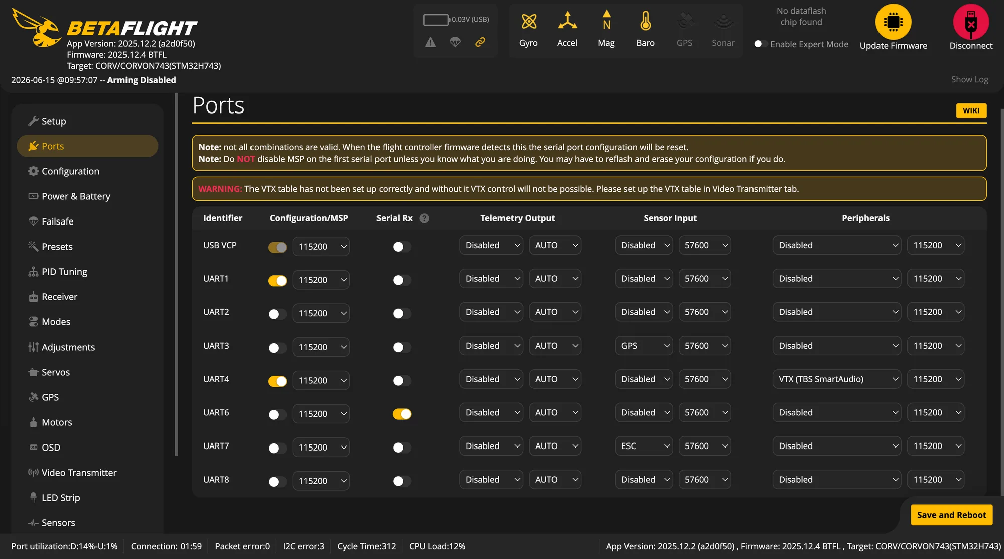
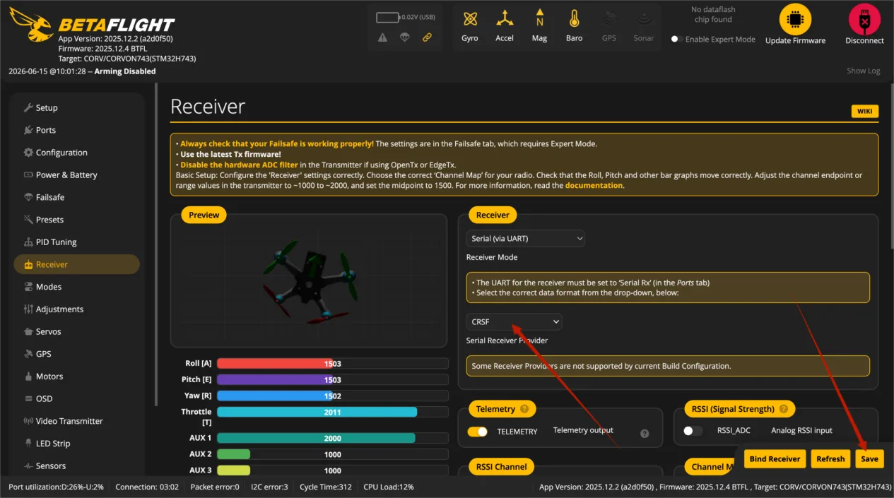
Receiver configuration: CORVON flight controller firmware enables RC on UART6 by default. After connecting the receiver to UART6, enable Serial RX on the Ports page, then select the corresponding protocol on the Receiver page. ELRS / TBS Crossfire usually uses CRSF, while SBUS receivers use SBUS.
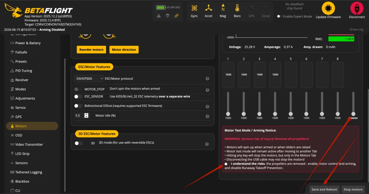
Motor test: before actual flight, enter the Motors page and test each motor one by one. Propellers must be removed before testing. Confirm that each motor number, position, and rotation direction match the software diagram. After adjustment, click Save and Reboot to save and restart.
Inverted flight controller setup: if the flight controller is installed upside down, keep the first gyro at the default CW 0 degrees. On the Configuration page, set Roll Degrees under Board Alignment to 180 degrees, then click Save and Reboot to save and restart.
BF Beginner Startup Flow
The following flow follows the actual tuning order. Betaflight is better suited for FPV drones and manual flight. Beginners should not install propellers before the first flight. First confirm connection, correct attitude, receiver response, failsafe stop, and correct motor and propeller directions, then proceed to takeoff.
Pre-build safety check: confirm that the flight controller arrow, mounting orientation, and nose direction are consistent. Do not reverse power polarity, and make sure solder joints are not cold or bridged. Connect the receiver, video transmitter, GPS, and ESC signal wires to the correct ports. Propellers must be removed at this stage, and all later motor tests must also be done without propellers.
Flash and connect the flight controller: use the CORVON online flasher or Betaflight Configurator to flash the corresponding target firmware. After flashing, power cycle the flight controller, open Betaflight Configurator, and connect by selecting Betaflight STM Electronics or the corresponding serial port.
Calibrate accelerometer and attitude: enter the Setup page, place the aircraft level, and click Calibrate Accelerometer. Gently lift the nose and tilt the airframe left and right to confirm that the model in the software moves the same way as the real aircraft. If the flight controller is inverted or rotated, set the corresponding angle in Board Alignment under Configuration.
Configure ports and receiver: when the receiver is connected to UART6, enable Serial RX for UART6 on the Ports page. Then enter the Receiver page and select the protocol. ELRS / TBS Crossfire generally uses CRSF, while SBUS receivers use SBUS. After turning on the transmitter, the Roll, Pitch, Yaw, and Throttle channels should follow stick movement, with mid point around 1500, low point around 1000, and high point around 2000.
Set flight modes and arm switch: enter the Modes page and set at least the ARM switch. Beginners are also advised to set Angle or Horizon self-level mode and use self-level mode for the first hover. It is also recommended to assign Beeper to an independent switch for easier model finding and troubleshooting.
Set failsafe: Failsafe must be confirmed. When the transmitter is turned off, Betaflight should detect RXLOSS. Standard FPV drones usually use Drop so output stops immediately after signal loss. If GPS Rescue is used, GPS, return altitude, rescue angle, and throttle range must be configured correctly; do not rely on it just by enabling the switch.
Check motor order and direction: keep propellers removed, connect the battery to power the ESCs, enter the Motors page, confirm the safety checkbox, and test each motor one by one. Motor number, position, and rotation direction must match the BF diagram. If the order is wrong, adjust it with Reorder motors. If the direction is wrong, adjust it with Motor direction or an ESC tool.
Check battery, voltage, and OSD: after connecting the battery, check whether the voltage shown in the software is close to the actual voltage. If the value is clearly incorrect, check Power & Battery settings first. Before the first flight, confirm that low-voltage warning, beeper, OSD voltage, and flight time display all work normally.
Install propellers last: install propellers only after all no-prop tests are complete. Do not install propellers upside down or on the wrong motor; motor direction and propeller direction must match. After propellers are installed, do not test throttle on a desk. Any test with propellers installed must be done in an open area.
Final pre-flight check: the field must be open and away from people, vehicles, and high-voltage lines. Make sure the transmitter has enough battery, the aircraft battery is secured, and the arms, screws, and propellers are tightened. Before arming, check the top status bar. If there is a red error or arming-disabled warning, fix the cause first and do not force takeoff.
First takeoff: place the aircraft on level ground with the tail facing you. Switch to Angle mode first, then arm. Slowly raise throttle and hover 1 to 2 meters above the ground. Do not fly far at the beginning. After confirming there is no obvious flipping, drifting, shaking, or abnormal motor sound, make small forward, backward, left, and right movements, then land slowly. After landing, disconnect power and check motor temperature, propellers, screws, and frame before deciding whether to continue flying.
Beginner Quick Check
First confirm the USB cable supports data transfer, then check browser permission, driver, and serial port selection. For DFU flashing, hold BOOT before plugging in USB.
Check whether the receiver is bound, whether Serial RX is enabled on UART6, and whether the correct Receiver protocol is selected.
First check the Betaflight top status bar or arming disable flags in CLI. Common causes include throttle not at minimum, no receiver signal, excessive tilt angle, Failsafe, or sensors not ready.
First check flight controller orientation, motor order, motor direction, and propeller direction. Any one of these being wrong can cause a flip.
Without propellers, the flight controller will try to correct attitude, so motor speeds not matching exactly is normal. What really needs confirmation is whether motor order and direction are correct.
First check whether screws, propellers, motors, and the frame are loose or deformed, then consider filter and PID adjustments. Beginners should not make large PID changes at the start.