Remove propellers before bench setup. Use MAVLink output from the module for PX4 / ArduPilot and MSP output for INAV / Betaflight. UART4 and TELEM 2 are examples: use the port actually wired to the module. On ArduPilot 4.7+, MAVx identifies the MAVLink channel, not the SERIALx port number. Verify the channel mapping before changing options. Screenshots illustrate the UI and are not proof of flight validation; names and available features depend on the installed firmware build.
PX4 Configuration
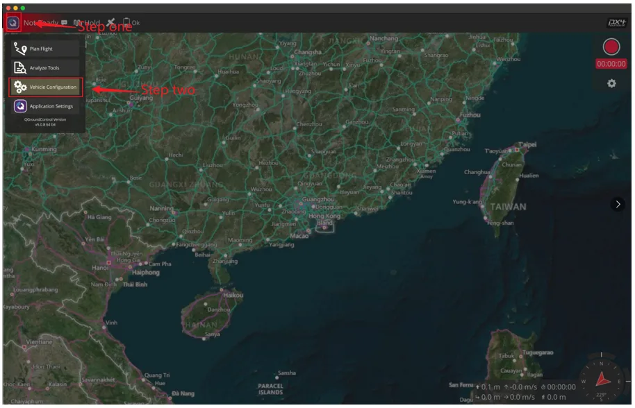
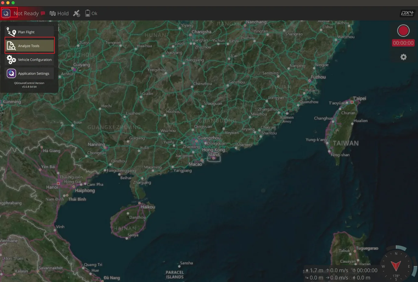
Open the tool and select Vehicle Configuration;
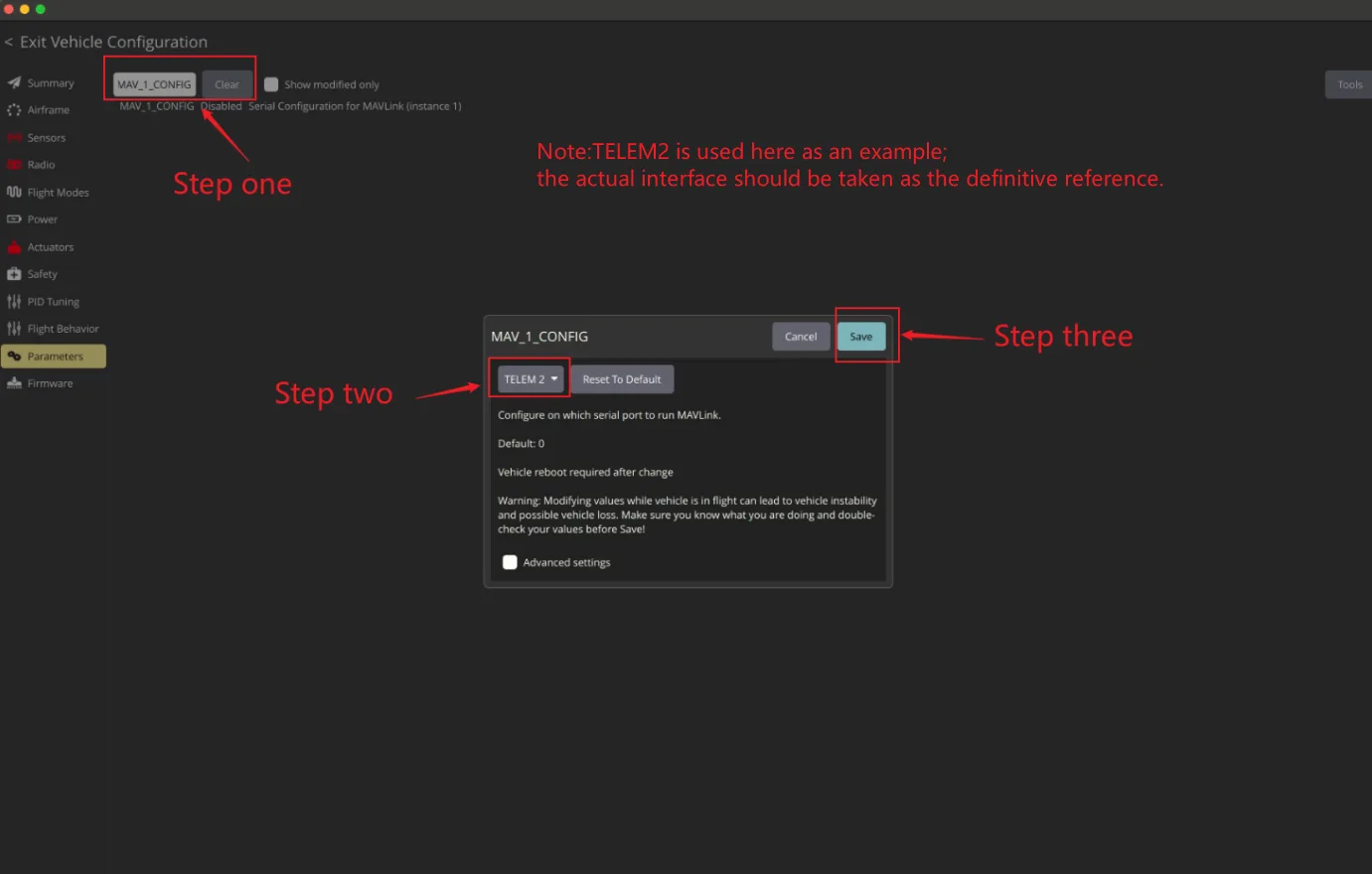
Set MAV_1_CONFIG to TELEM 2 and save;
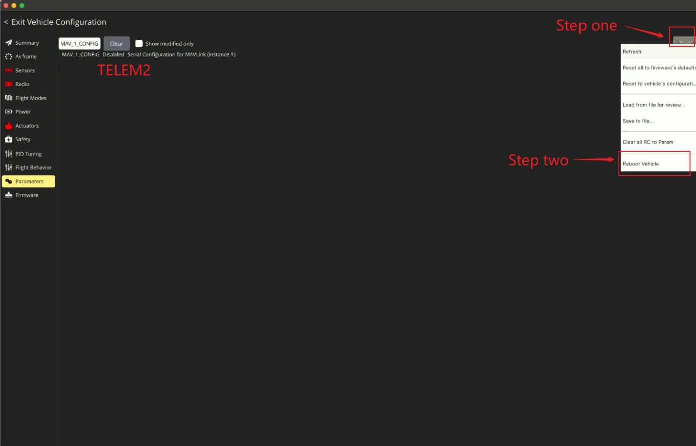
Click Tools, then click Reboot Vehicle;
Set MAV_1_MODE to Normal and save;
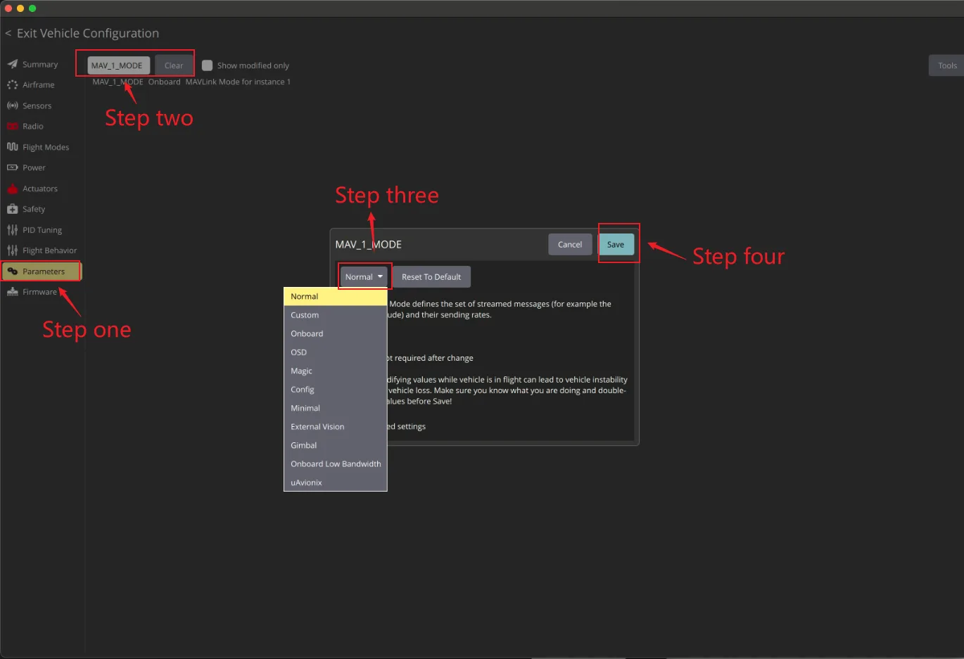
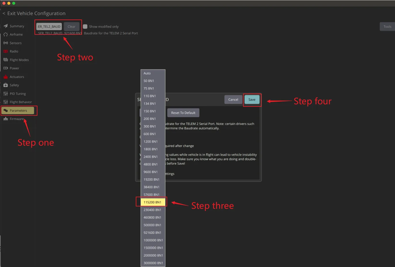
Set SER_TEL2_BAUD to 115200 8N1 and save it;
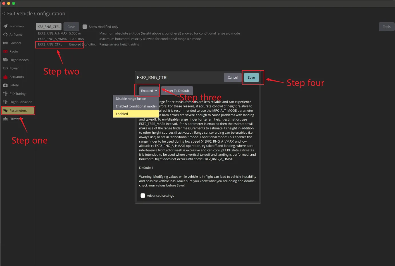
Optional height-fusion setup: leave EKF2_RNG_CTRL unchanged for the communication check in step 8. The illustrated Enabled setting enables continuous range fusion; choose it only after assessing the installed PX4 version, mounting, reliable sensor range and flight conditions. This is not a required step for receiving sensor messages.
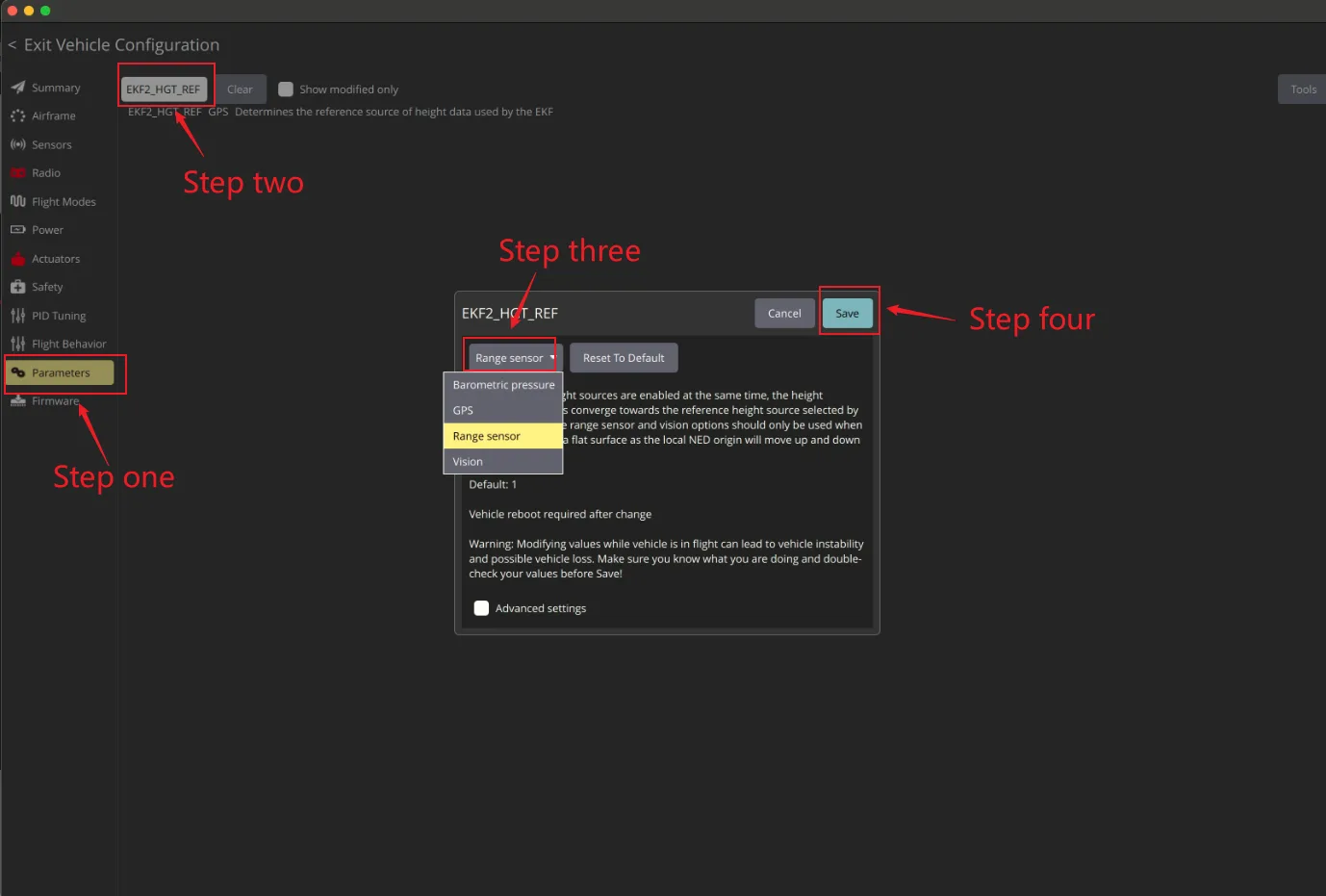
Optional height reference: EKF2_HGT_REF = Range sensor is intended only for operation over a flat surface within the reliable range of a downward-facing sensor. Terrain changes move the local height reference. Keep the existing height reference for the communication check; do not copy this setting as a general flight configuration.
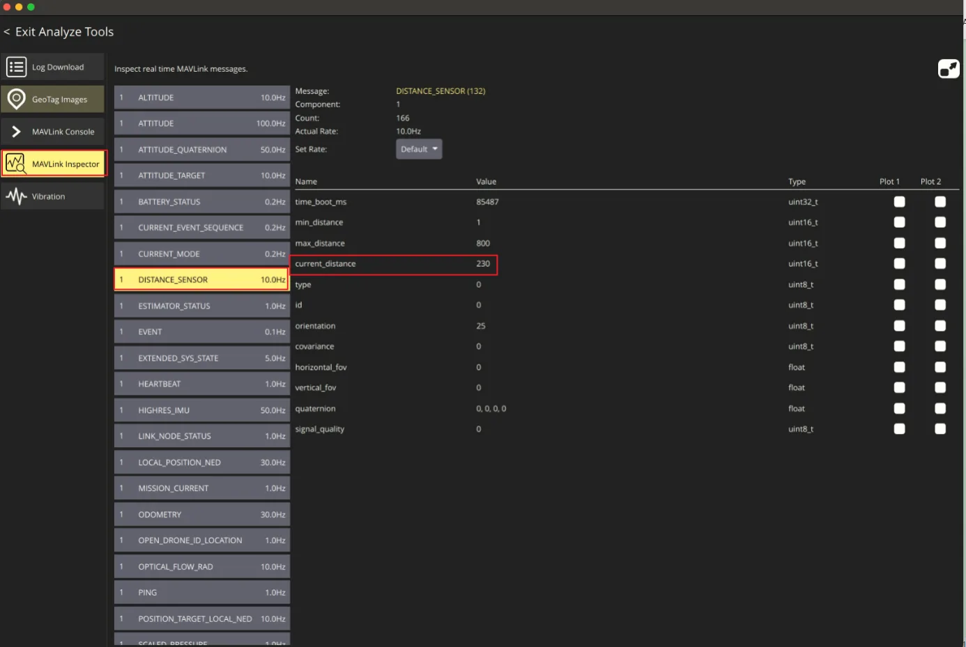
After the configuration is completed, restart the flight controller. You should be able to see the DISTANCE_SENSOR messages in the MAVLink Inspector page of QGC. It's fine as long as there is a change in the values. Note that the messages displayed on the QGC are sent by the flight control. The message frequency is not the same as the data frequency of the sensor. This frequency is determined by the Settings of the flight control and the speed of the data link, and is mainly used for observation. The number of the message frequency is not important.
APM Configuration
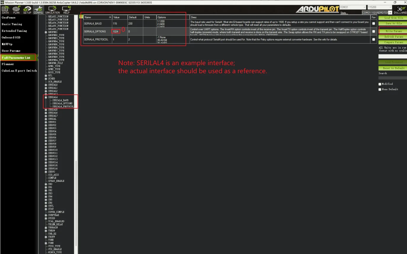
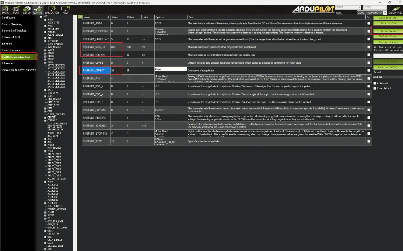
In Mission Planner, set the corresponding serial port baud rate SERIAL4_BAUD to 115(115200), and set the options parameter according to the firmware version: for 4.7 and later, use MAVx_OPTIONS and enable bit 1 (mask 2, disable MAVLink forwarding) while preserving other bits; for 4.6 and earlier, use SERIALx_OPTIONS and enable bit 10 (mask 1024, private MAVLink channel) while preserving other bits. Then set the serial port protocol value SERIAL4_PROTOCOL to 1(Mavlink1). Click "Write Params" to save;
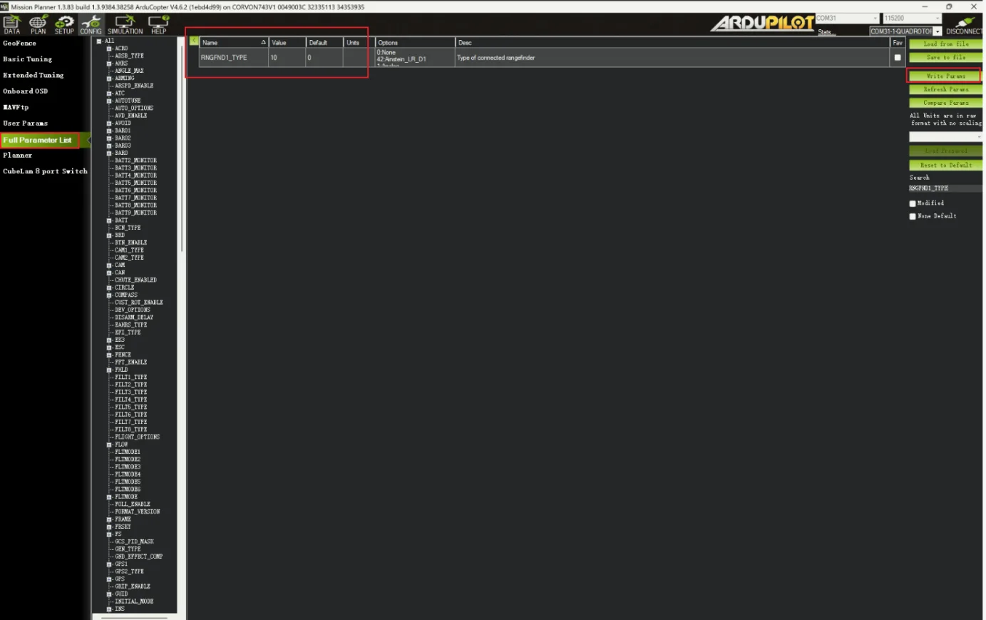
Set the RNGFND1_TYPE value to 10 and save it; click Write Params to save, then click Refresh Params.
Restart the flight controller after enabling the rangefinder. For ArduPilot 4.7 and later, set RNGFND1_MAX to 8 and RNGFND1_MIN to 0.02 (metres). For 4.6 and earlier, set RNGFND1_MAX_CM to 800 and RNGFND1_MIN_CM to 2 (centimetres). Save the settings. Screenshots show the older parameter names.
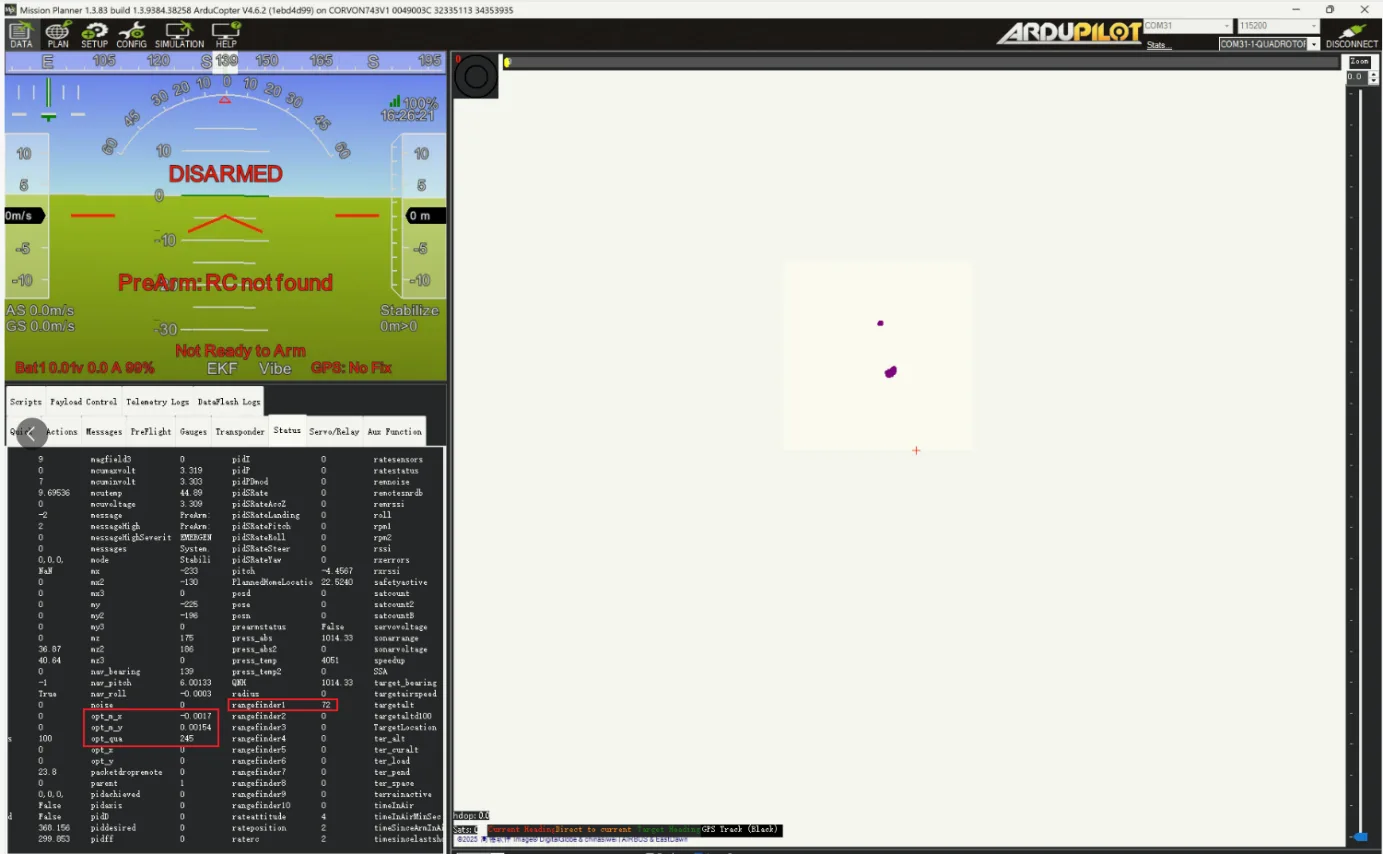
On the status page, you can see the values of rangefinder1.
INAV Configuration
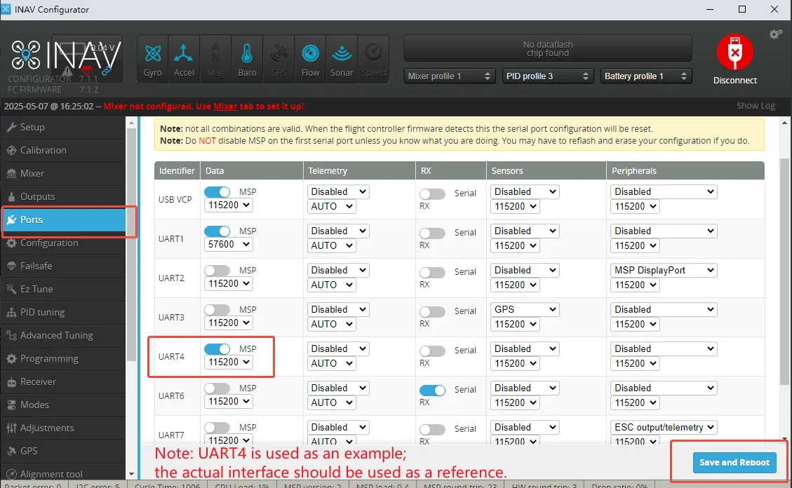
Open the Ports interface, enable the MSP function for the corresponding serial port (we are connected to UART4), save, and restart.
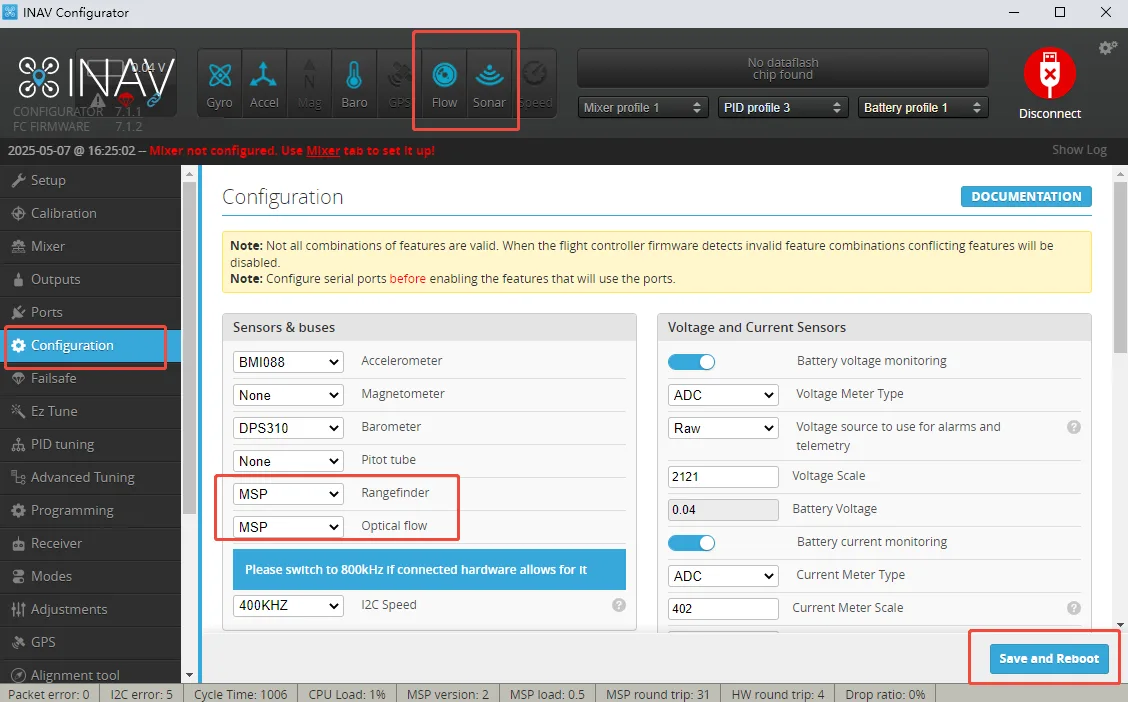
In Configuration, set Rangefinder to MSP, save and restart. CV08 is distance-only: do not enable optical flow for this module or expect a Flow indicator. The shared screenshot also shows optical-flow settings, which do not apply to CV08.
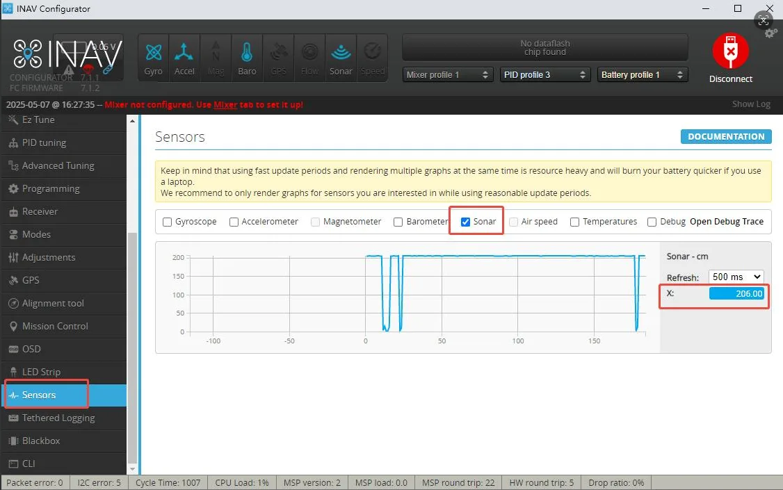
On the Sensors screen, tick the Sonar option; if configured correctly, you should see the waveform and X-values changing:
ToF Betaflight Configuration
The Betaflight firmware must include the rangefinder feature and the specified driver. Receiving rangefinder data does not establish altitude-hold or obstacle-avoidance capability.
Switch ToF to MSP mode.
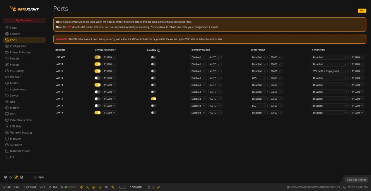
On the Ports page, enable MSP for UART4, then save and reboot.
Enter the following commands in CLI, one line at a time, and save:
set rangefinder_hardware = MTF01P
feature RANGEFINDER
save
View rangefinder data:
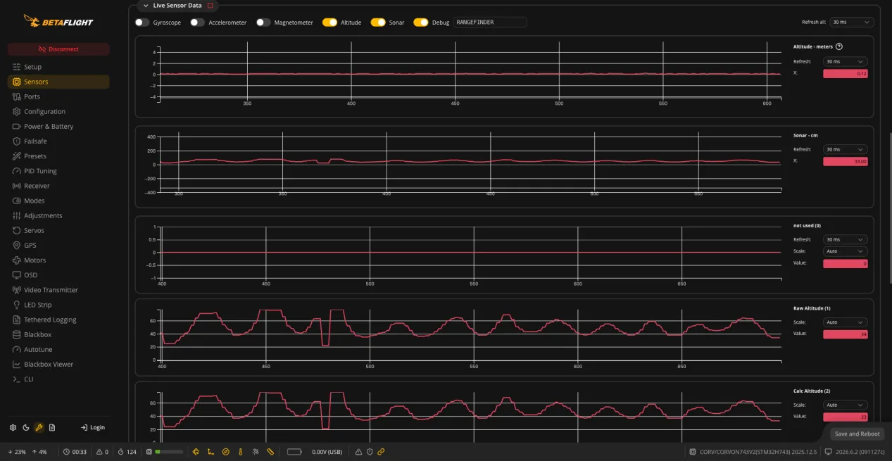
set debug_mode = RANGEFINDERsaveVIEW DATAOn the Sensors page, view Sonar - cm, Raw Altitude, and Calc Altitude.