Software Download
INAV Configurator
Scan the QR code below for the Corvon Discord server.


One-Click Firmware Flashing
Copy the CORVON web flasher link and open it with Chrome or another browser that supports WebUSB.
https://flasher.corvon.tech/
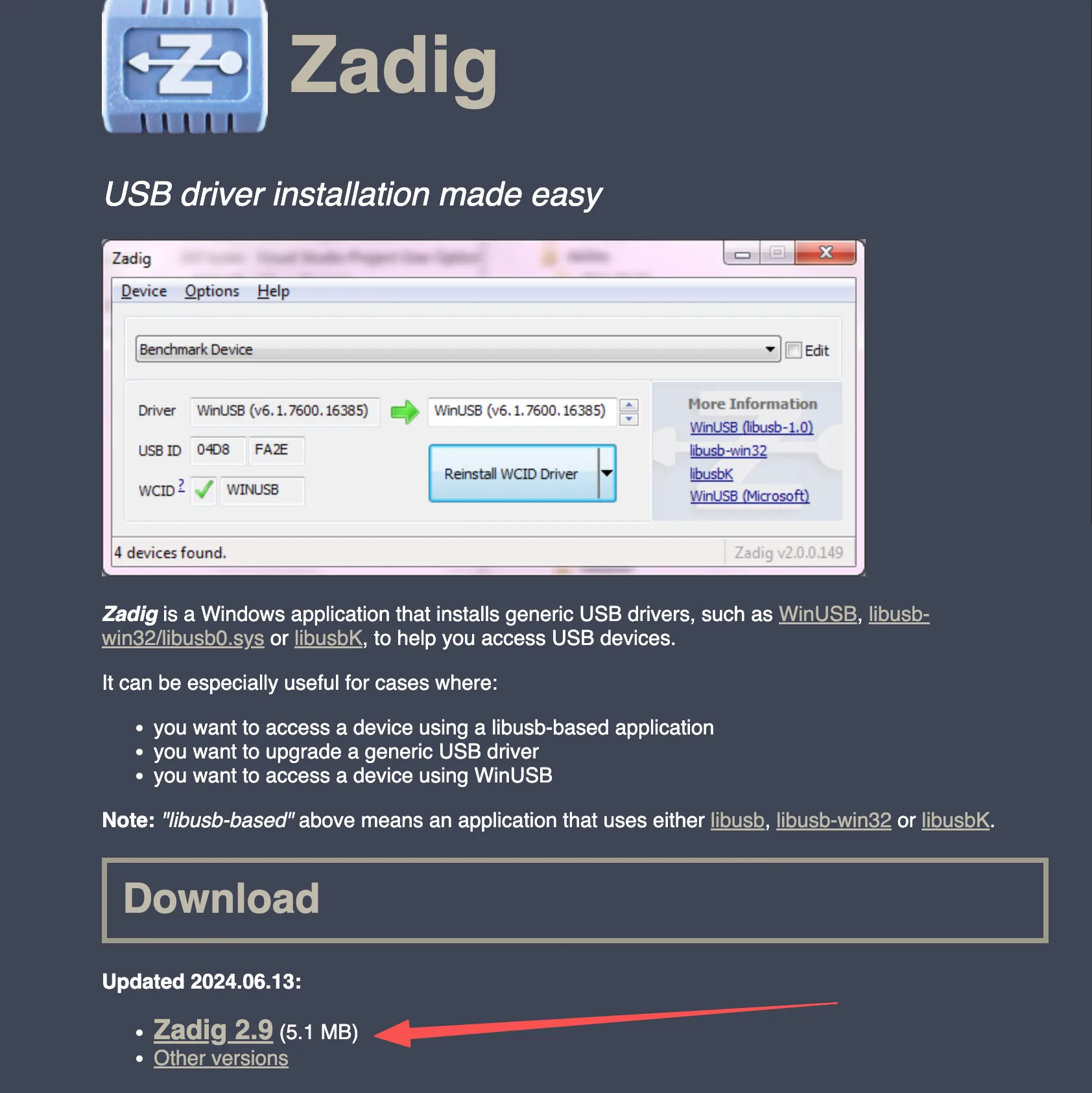
Before flashing, install Zadig to install the DFU driver for the flight controller. Refer to the image below for the download location.
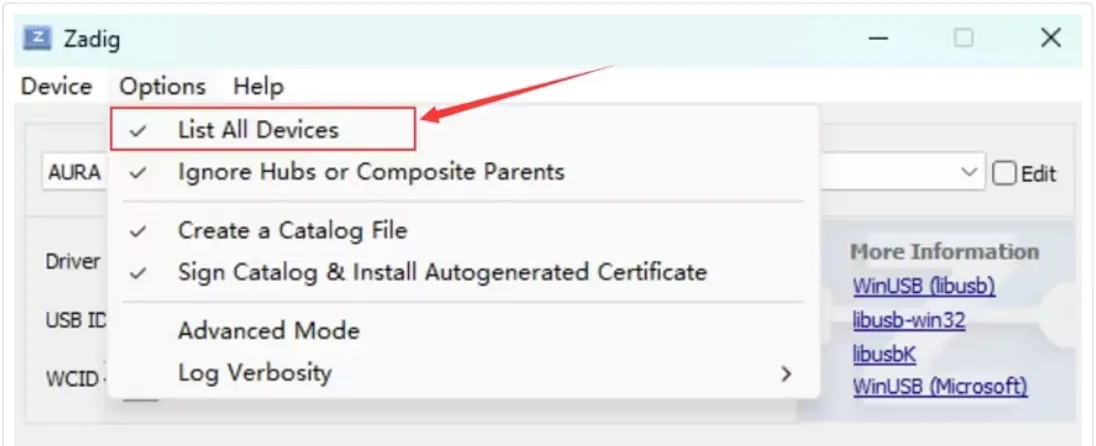
Open the Zadig download entry in the upper-right corner of the web page. After launching Zadig, open the Options menu and check List All Devices.
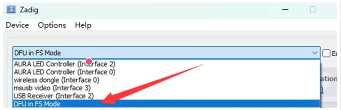
Expand the device list and select DFU in FS Mode. If the flight controller uses an STM32F405 MCU, the device name may appear as STM32 BOOTLOADER. If the device is not listed, confirm that the BOOT button was held before plugging in USB, and check that the USB cable supports data transfer.
Click Install Driver to install the WinUSB driver.
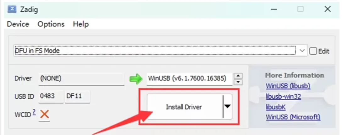
Wait a few minutes. After the driver is installed, open Windows Device Manager. If DFU in FS Mode appears, the computer has correctly recognized the flight controller in DFU mode.
After the flight controller enters DFU mode, flash the firmware using the steps below.
Prepare the CORVON flight controller and a USB-A to USB-C data cable.
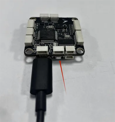
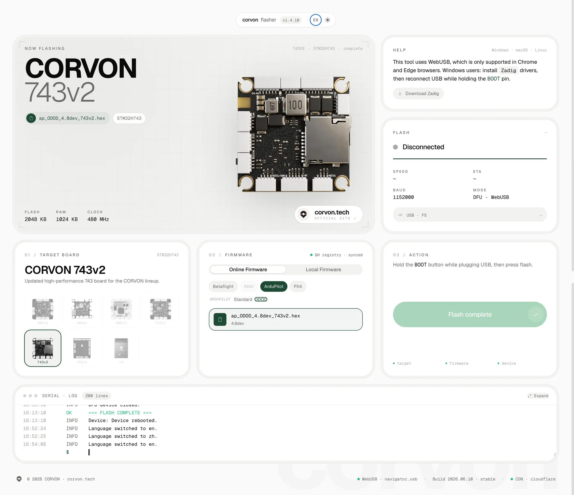
Open the online flasher page. Hold the BOOT button near the flight controller USB port first, then plug in the USB cable to connect it to the computer. Release the button about 2 seconds after the flight controller powers on. Then select the target flight controller and corresponding firmware, click flash, choose the recognized device in the pop-up serial/device selection window, and wait for flashing to complete.
Firmware on the online flashing page is updated continuously. Use the version shown on the web page as the reference.
INAV Basic Flight Controller Tuning
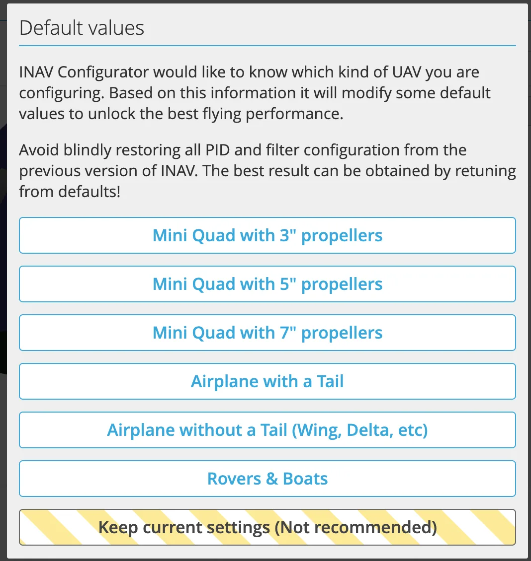
Select the airframe: choose the corresponding airframe based on aircraft type. For example, select Quad for a multirotor, or the corresponding tailed or tailless type for a fixed-wing aircraft.
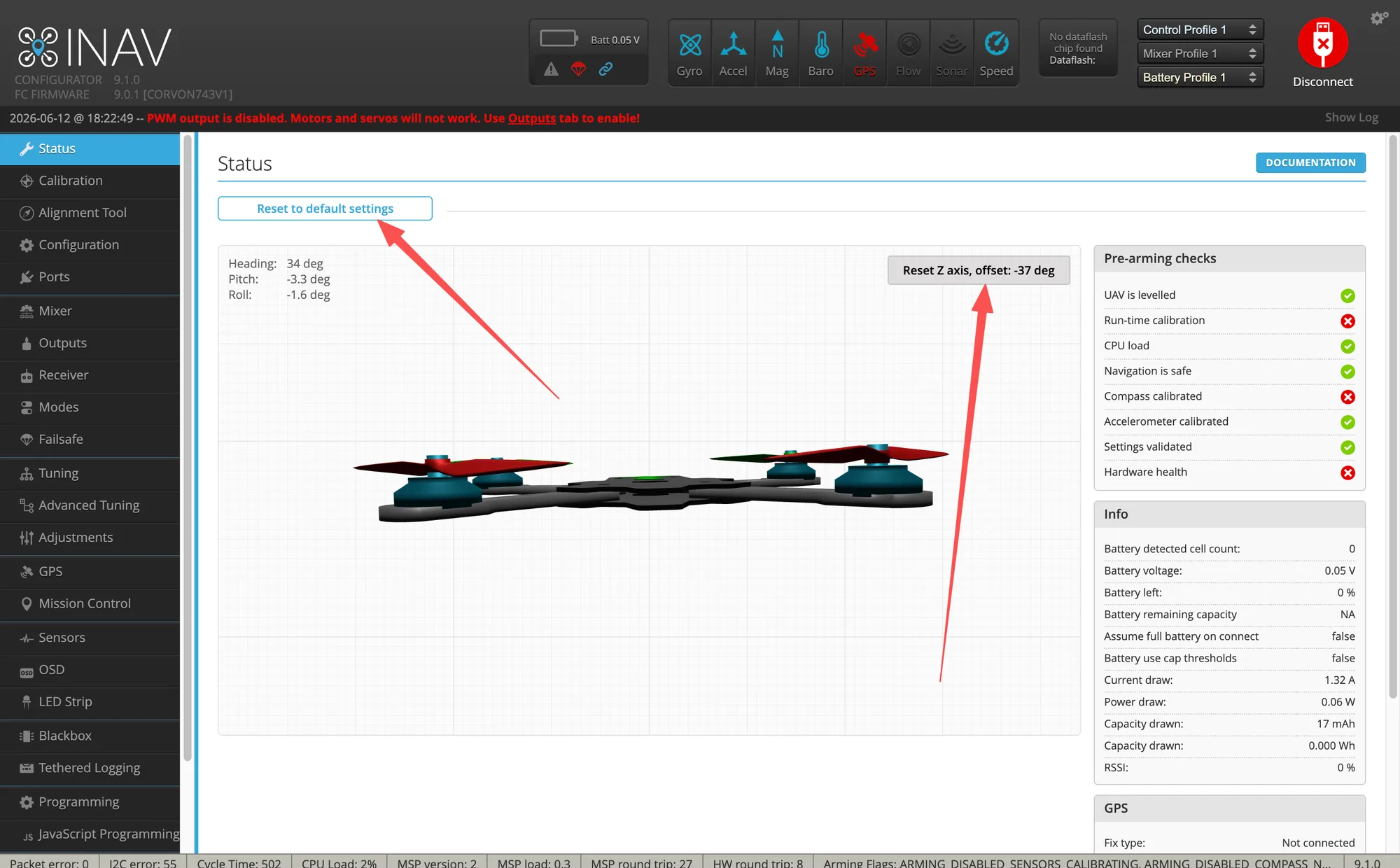
Reset the Z axis: place the flight controller level on a stable table, then perform the reset so the level attitude shown in the software matches the real aircraft.
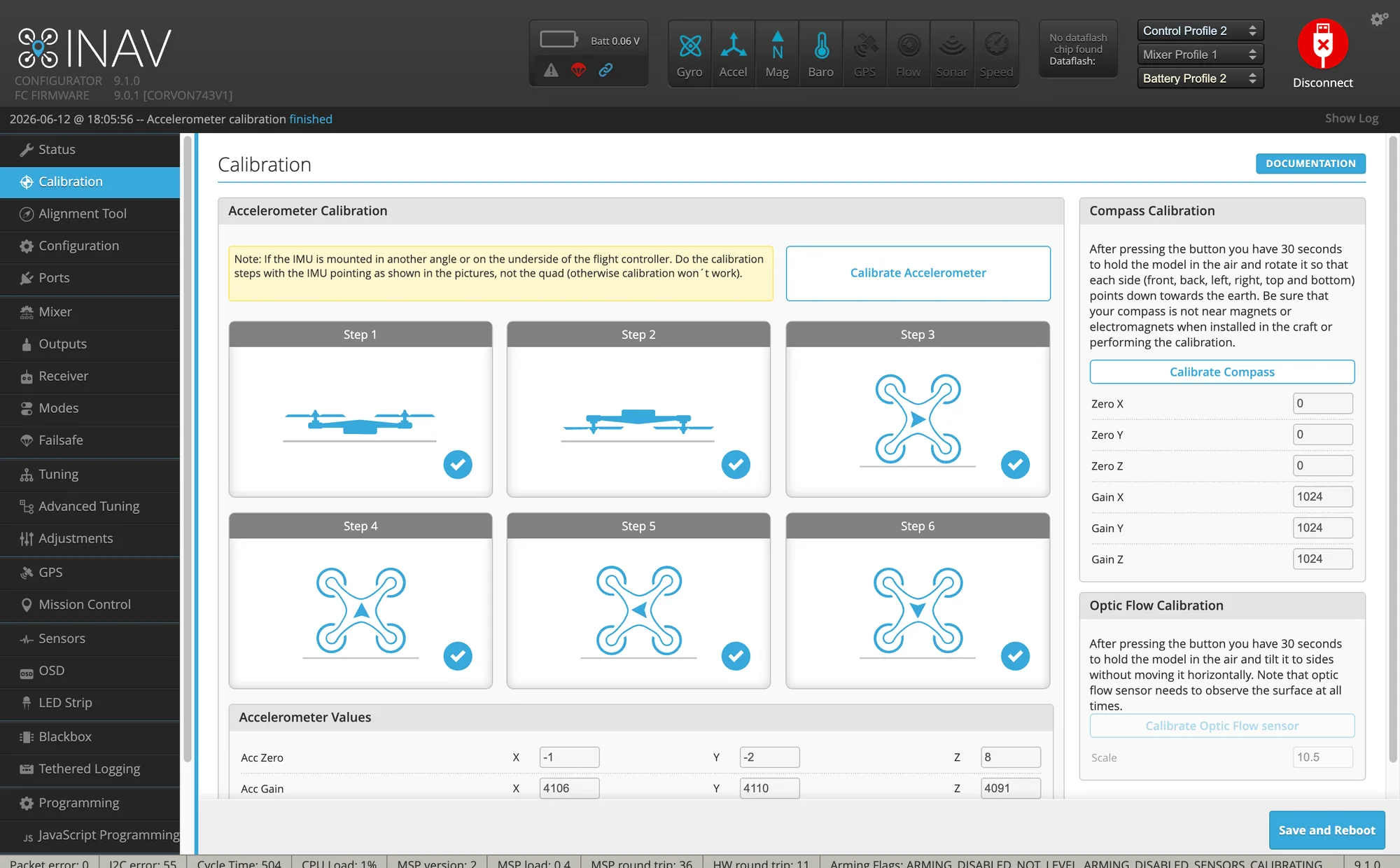
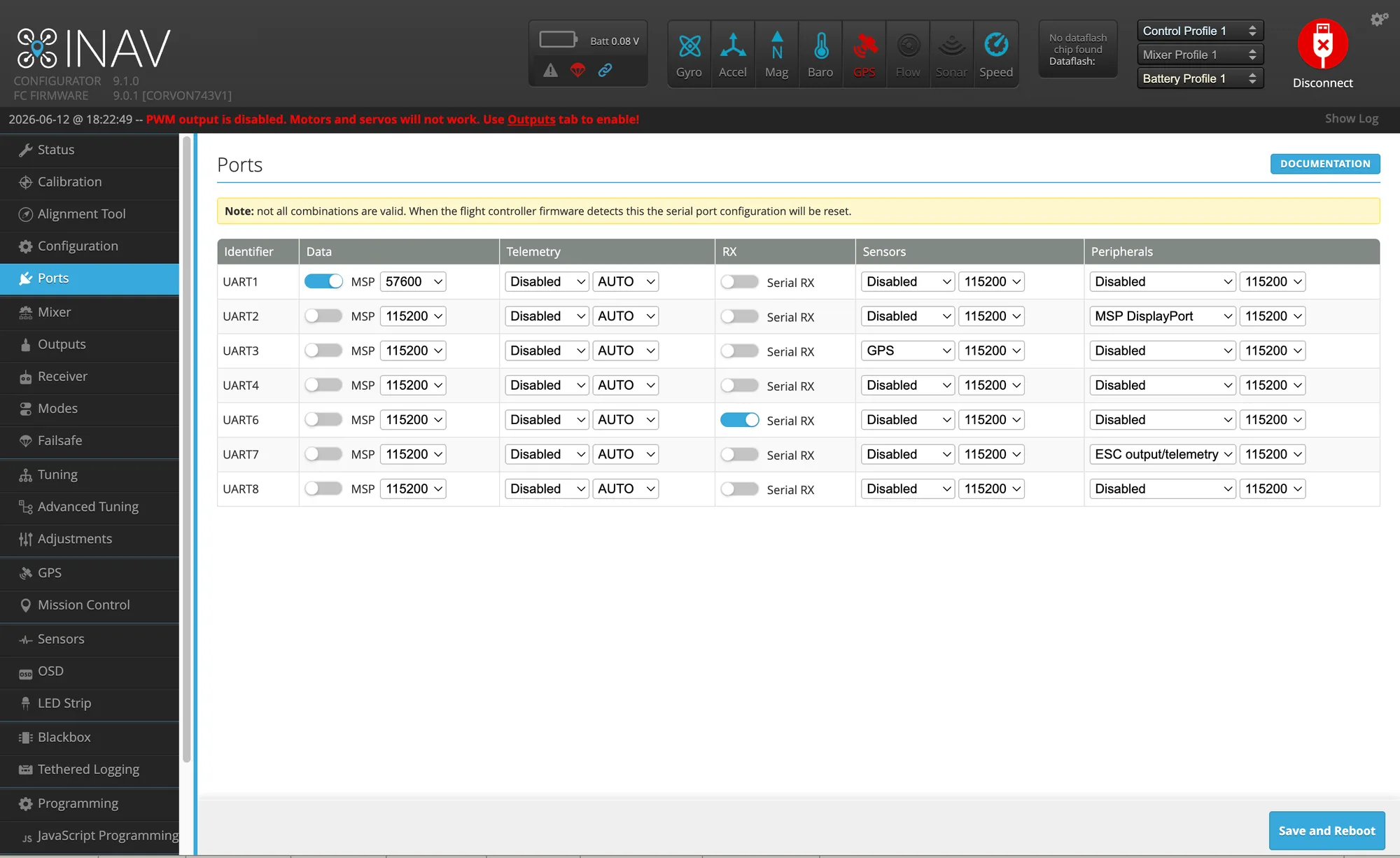
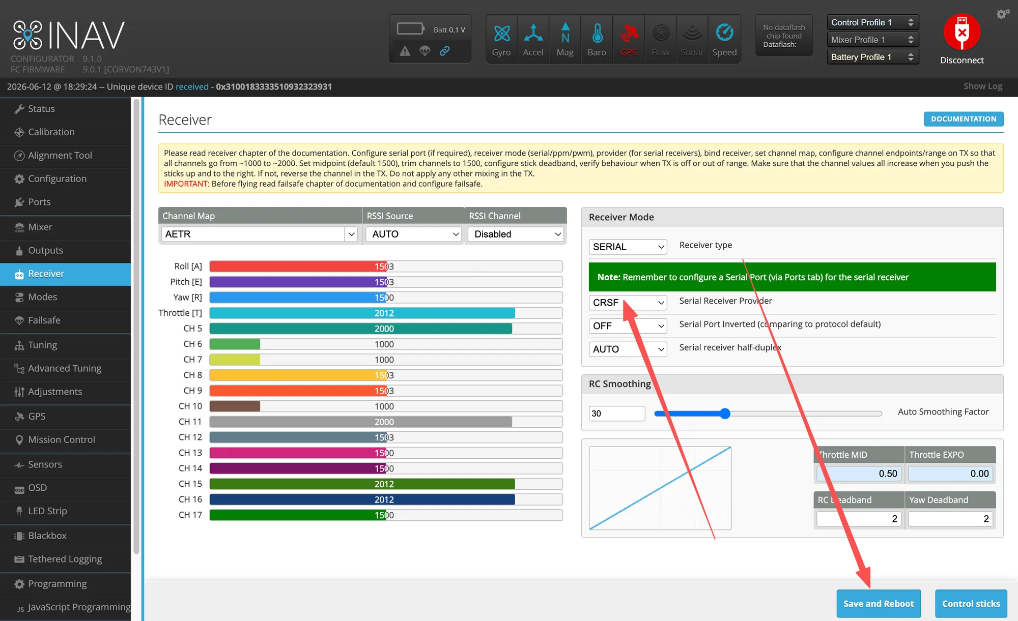
Sensors and receiver: follow the on-screen prompts to complete accelerometer calibration. Models with a compass also need compass calibration. CORVON flight controller firmware enables RC on UART6 by default. After connecting the receiver to UART6, enable Serial RX on the Ports page and select the corresponding protocol on the Receiver page.
INAV Motor Order Adjustment
Connect the flight controller: use a USB data cable to connect the flight controller to the computer, then open INAV Configurator.
Enter motor settings: open the Mixer page from the left menu.
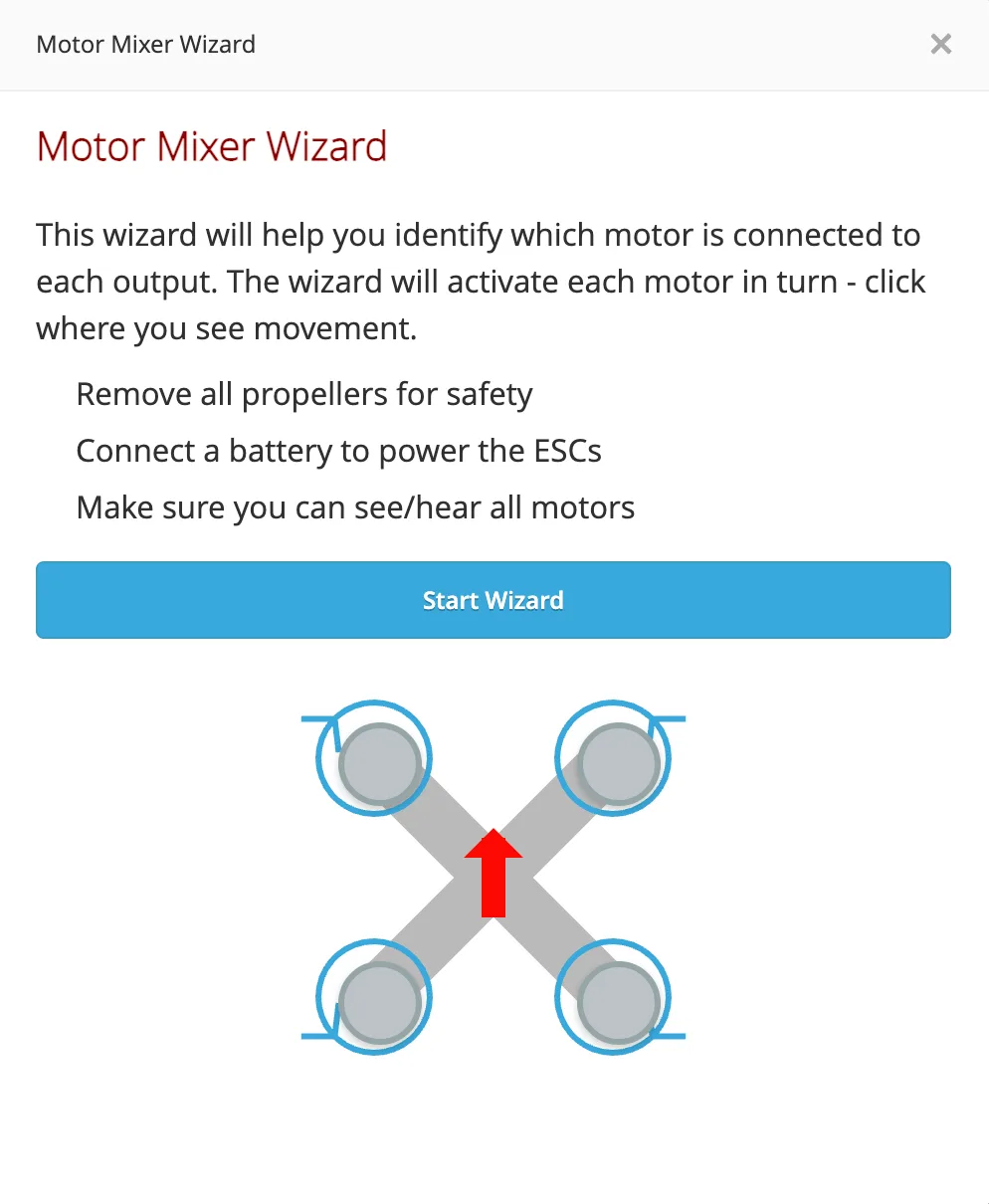
Open the motor wizard: on the Mixer page, click Motor Mixer Wizard on the right.
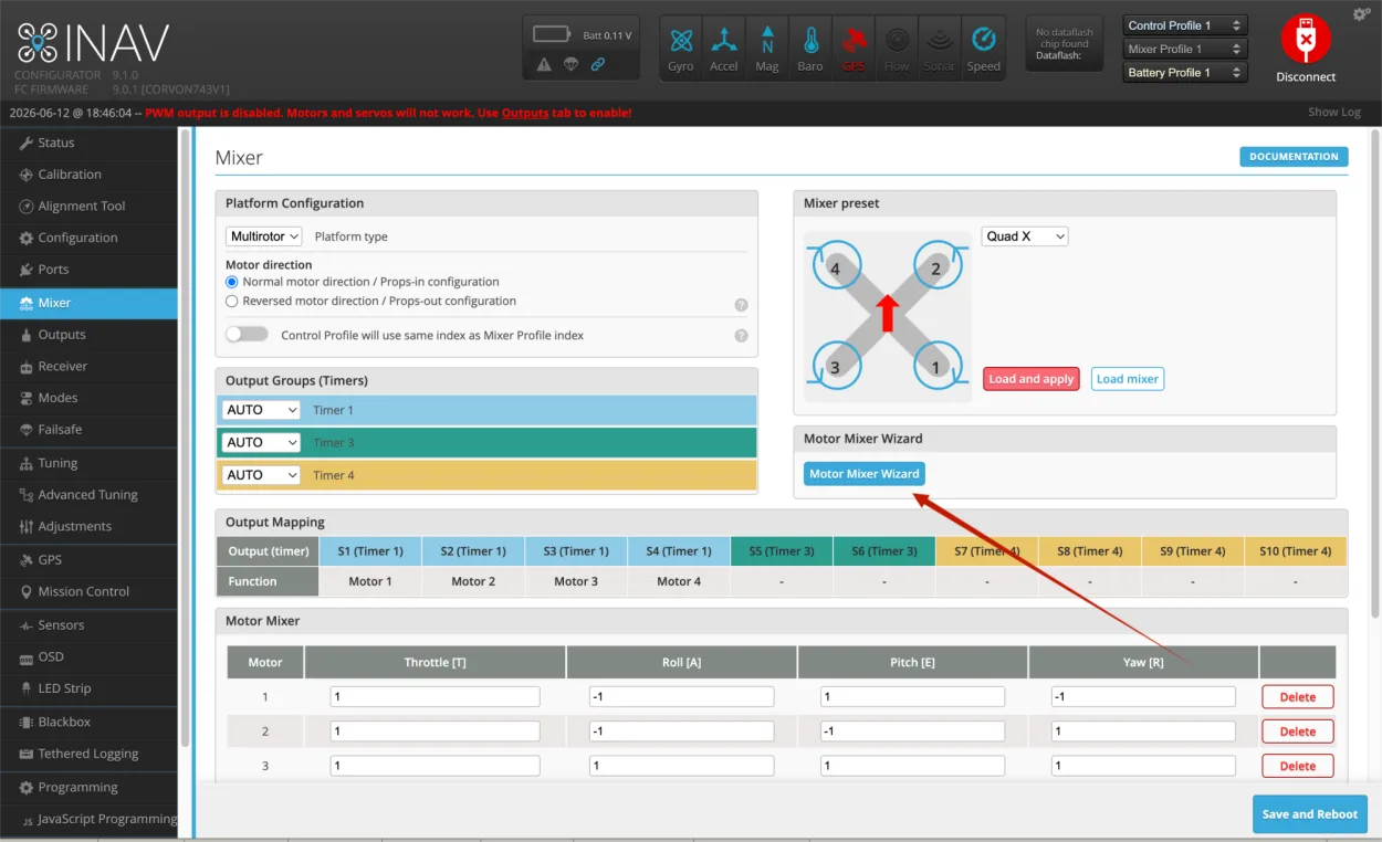
In the pop-up Motor Mixer Wizard window, follow the interface prompts to confirm each motor position one by one, and adjust the motor order according to the actual position.
Save settings: after adjustment is complete, click Save and Reboot to save the settings and reboot the flight controller.
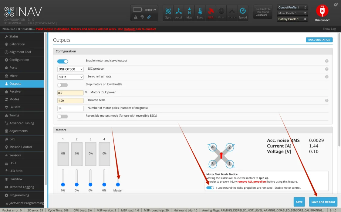
Test and confirm: before actual flight, open the Outputs page and test each motor one by one. Confirm that each motor works in the order and position shown in the software. After adjustment, make sure to save and reboot.
Complete Workflow from Setup to Takeoff
The following workflow follows the actual setup sequence. Beginners should not install propellers before the first flight. First confirm normal connection, correct attitude, controllable RC input, reliable failsafe/stop behavior, and correct motor and propeller direction before takeoff.
Pre-installation safety check: confirm that the flight controller is mounted in the correct direction, with the arrow on the board pointing toward the nose. Do not reverse power polarity, and make sure solder joints are solid with no bridges. Connect the receiver, GPS, video transmitter, and ESC signal wires to the correct ports. Remove the propellers at this stage, and keep them removed for all later motor tests.
Connect the flight controller and confirm basic status: connect it to the computer via USB and open INAV Configurator. After connection, check the Status page first. Gently raise the nose or tilt the airframe left and right, and confirm that the model attitude in the software matches the real aircraft. If the direction is reversed, check the flight controller mounting direction or board orientation setting first.
Select the airframe and save default parameters: on the default parameter or Mixer-related page, choose the airframe that matches the aircraft. Select the corresponding Quad type for a quadcopter, or the tailed/tailless type for a fixed-wing aircraft. After selection, click Save and Reboot so INAV loads the base parameters for the airframe.
Complete sensor calibration: open the Calibration page, place the aircraft on a level table, then reset the Z axis and calibrate the accelerometer. If six-sided calibration is required, place the airframe in each orientation as prompted, and change orientation only after each step is complete. Models with a compass also require compass calibration. Keep away from computers, power cables, screwdrivers, and large metal objects during calibration.
Configure the receiver: CORVON flight controller firmware enables RC on UART6 by default. After connecting the receiver to UART6, confirm that Serial RX is enabled on the Ports page, then select the corresponding protocol on the Receiver page. ELRS/TBS Crossfire usually uses CRSF, while an SBUS receiver uses SBUS. After turning on the transmitter, the Roll, Pitch, Yaw, and Throttle channels should follow stick movement, with center around 1500, low around 1000, and high around 2000.
Set arming and flight modes: open the Modes page and set at least one ARM switch. Beginners should set Angle or Horizon self-level mode first. A three-position switch can be assigned to Angle, Horizon, and Acro. For the first flight, start with Angle mode. After setup, click Save, then return to the Status page and confirm that switch state changes are correct.
Set failsafe: Failsafe must be configured. For small aircraft without GPS, the usual action after signal loss is to cut throttle and descend. Only consider RTH for models with GPS after return altitude, Home point, and compass/GPS are correctly configured. During the first setup, do not rely on automatic return first; focus on confirming that INAV can detect failsafe status after the transmitter is turned off.
Check motor order and direction: keep propellers removed, connect the battery to power the ESCs, and test each motor one by one on the Outputs page. Motor number and position must match the software diagram, and rotation direction must meet the airframe requirement. If the order is wrong, adjust it with Motor Mixer Wizard. If rotation direction is wrong, reverse it in ESC settings first, or swap any two phase wires.
Check propeller direction: install propellers only after all motor tests are confirmed correct. Do not install propellers reversed. Use clockwise propellers on clockwise motors and counterclockwise propellers on counterclockwise motors. After installing propellers, do not casually throttle up on a table. Any test with propellers installed must be done in an open area.
Confirm battery and voltage: after connecting the battery, check whether the voltage shown in the software is close to the actual battery voltage. If the reading is clearly wrong, check battery settings or voltage scale first. Do not fly with incorrect voltage display. Low-voltage alarm, buzzer, and OSD voltage display should also be confirmed before the first flight.
Confirm GPS and compass: if the aircraft needs position hold, return-to-home, or mission features, wait outdoors in an open area until GPS positioning is stable. Do not test GPS return indoors. Before the first flight, confirm satellite count, positioning status, and that the Home point has been generated correctly before arming and takeoff.
Final pre-takeoff check: choose an open flying site away from people, vehicles, and high-voltage lines. Make sure the transmitter has sufficient battery, the aircraft battery is secure, and arms, screws, and propellers are tightened. If the Status page still shows red errors, check Arming Flags first and do not force arming. Common reasons for arming failure include throttle not at minimum, no receiver signal, sensors still calibrating, the flight controller not level, or safety checks not passed.
First takeoff: place the aircraft on level ground with the tail facing you. Switch to Angle mode first, then arm. Slowly raise throttle and hover 1 to 2 meters above the ground. Do not fly far at the start. After confirming there is no obvious roll-over tendency, drift, vibration, or abnormal motor sound, make small forward/backward/left/right movements and then land slowly. After landing, disconnect power and check motor temperature, propellers, screws, and frame before deciding whether to continue flying.
Beginner Quick Troubleshooting
Check Arming Flags on the right side of the Status page first, then handle each item as prompted. Do not blindly change parameters.
Check whether the receiver is bound, whether Serial RX is enabled on UART6, and whether the Receiver protocol is selected correctly.
Check motor order, motor rotation direction, propeller direction, and flight controller orientation first. Any one of these being wrong can cause a flip.
With propellers removed, the flight controller may try to correct attitude, so different motor speeds are normal. What really needs confirmation is whether motor order and direction are correct.
Wait outdoors in an open area. Keep the GPS antenna away from video transmitters, power cables, and carbon plates. Do not judge positioning performance indoors or near a window.