APM (Mission Planner) Servo Configuration Tutorial
Servo Wiring
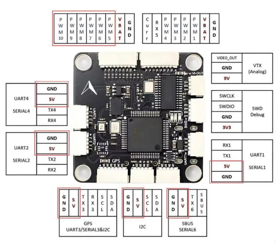
Take the CORVON743 as an example:
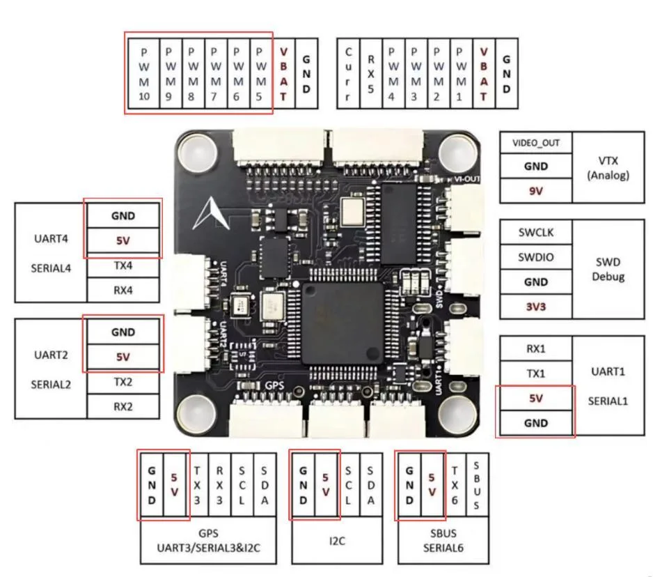
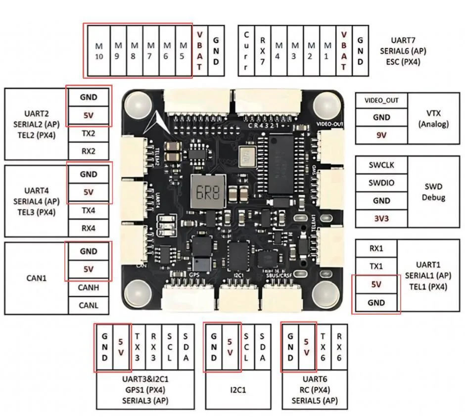
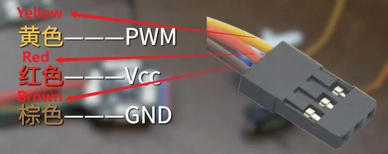
• Servo data PWM should be connected to one of the PWM5-10 pins on the flight controller port.
• Servo data GND should be connected to any GND pin on the flight controller.
• Servo data VCC can be connected to one of the VCC pins within the red-circled wire group on the flight controller port, as shown below.

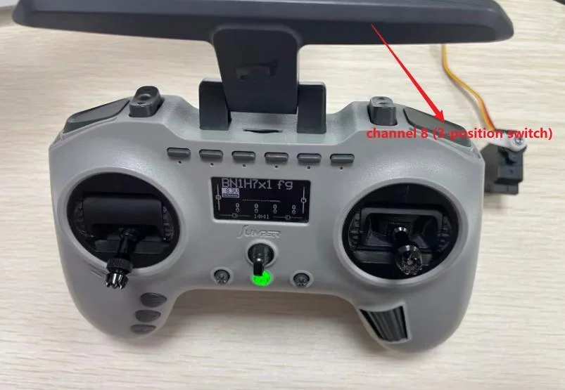
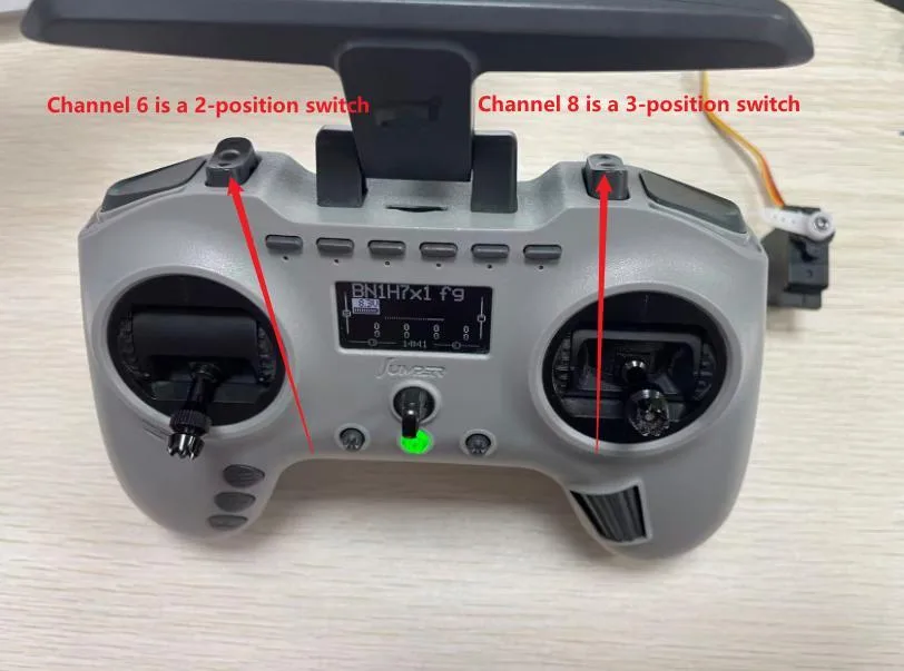
Open the APM (Mission Planner) ground station, connect the flight controller to the transmitter, select Initial Setup > Mandatory Hardware > Servo Output, and assign the corresponding port to any desired channel on the transmitter. For example, if the servo is connected to PWM5 on the flight controller and you want to control it with channel 8 (3-position switch) on the transmitter, modify the settings as shown below.
Once configured, the servo can be operated via the transmitter.
PX4 (QGroundControl) Servo Configuration Tutorial
Servo Wiring
Take the CORVON743 as an example:
• Servo data PWM should be connected to one of the PWM5-10 pins on the flight controller port.
• Servo data GND should be connected to any GND pin on the flight controller.
• Servo data VCC can be connected to one of the VCC pins within the red-circled wire group on the flight controller port, as shown below.

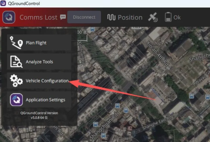
Open the PX4 (QGroundControl) ground station, go to Vehicle Configuration, and select the transmitter.
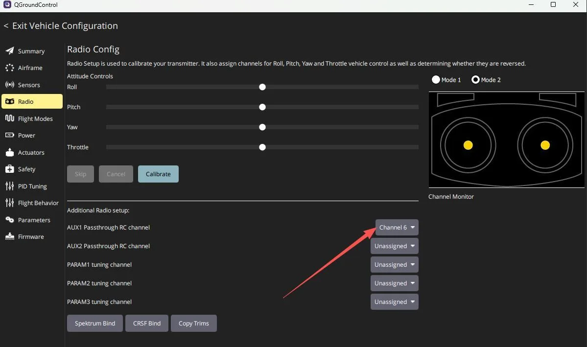
Set AUX1 to any channel on the transmitter, such as channel 6 with a 2-position switch. After setting, select Actuators.
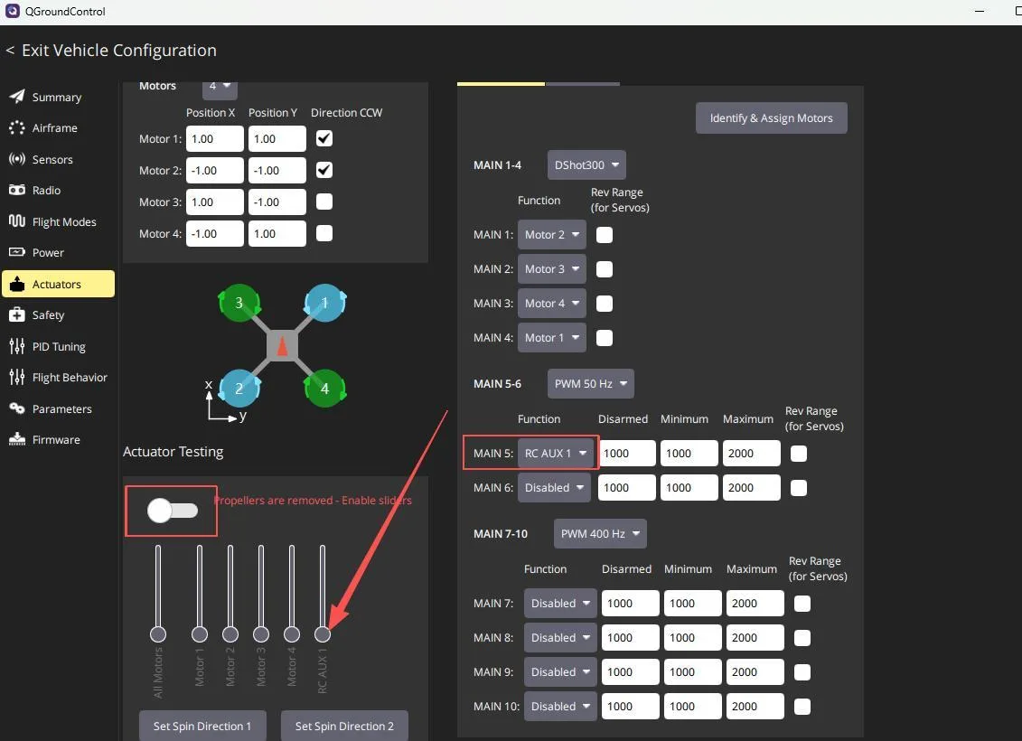
Set Port 5 to AUX1, which corresponds to channel 6 on the transmitter. The Actuator Testing section will then show an output. With the servo powered, moving the slider will drive the servo accordingly. Once configured, the servo can be operated via the transmitter.

INAV Servo Configuration Tutorial
Servo Wiring
Take the CORVON743 as an example:
• Servo data PWM should be connected to one of the PWM5-10 pins on the flight controller port.
• Servo data GND should be connected to any GND pin on the flight controller.
• Servo data VCC can be connected to one of the VCC pins within the red-circled wire group on the flight controller port, as shown below.
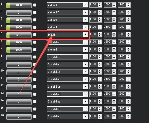
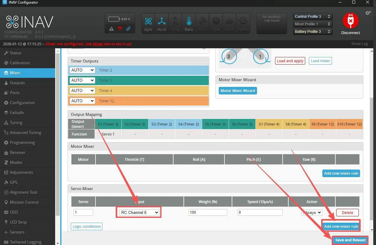
Open the INAV ground station and select the corresponding port to connect. After connection is successful, go to Mixer, add a new mixing rule, assign it to any transmitter channel, such as channel 6 with a 2-position switch, then save and reboot.
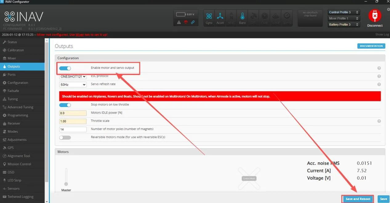
Select Output, enable motor and servo output, then save and reboot.
After reboot, scroll down the page and enable Live Mode. Save and reboot again. Once configured, the servo can be operated via the transmitter.