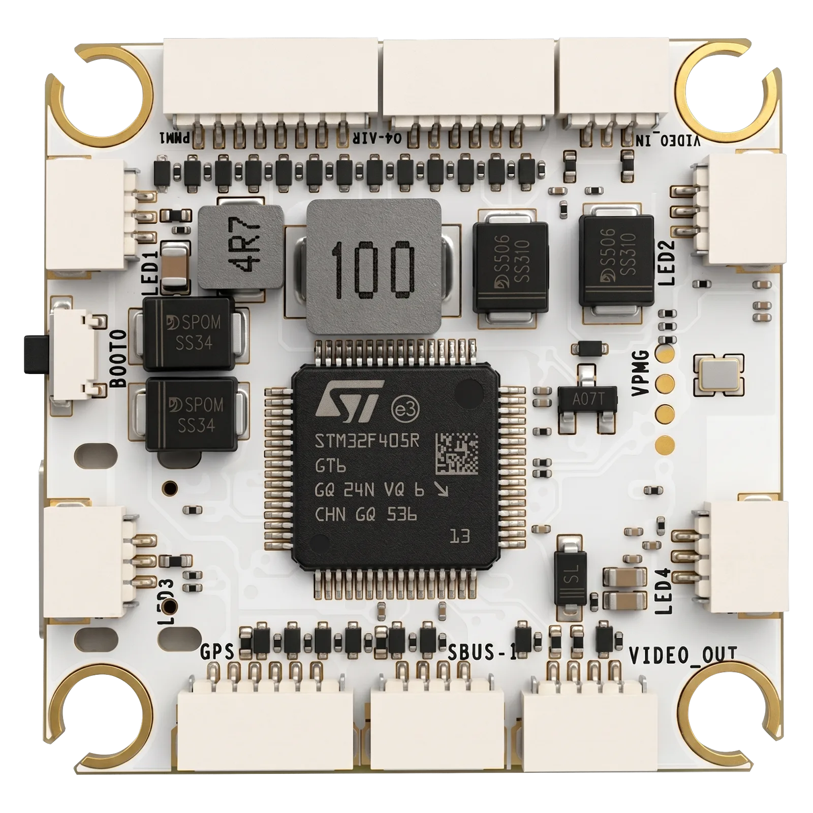
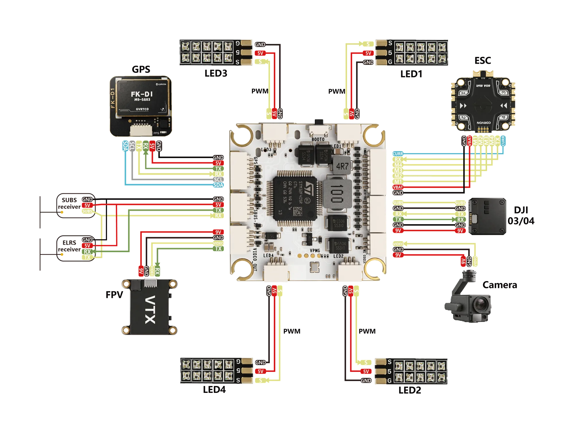
The CORVON 405v3 is a compact 36 × 36 mm FPV flight controller built on the STM32F405RGT6 Cortex-M4 MCU at 168 MHz with 1 MB flash. A high-accuracy ICM42688-P IMU pairs with an SPL06 barometer for stable altitude hold and reliable flight, while integrated AT7456E OSD overlays telemetry on the analog video feed. 6 UARTs, I²C, and 10 PWM outputs (CH1–8 DShot-capable) drive a complete FPV stack — ESC, GPS, receiver, VTX, and DJI air unit. Wide 2S–10S input feeds onboard 5V · 3A and 9V · 3A BEC rails, with an onboard TF card slot for blackbox logging. Runs INAV and Betaflight.
| SKU | CORVON 405v3 |
|---|---|
| MCU | STM32F405RGT6 · Cortex-M4 · 168 MHz |
| Flash / RAM | 1024 KB / 192 KB |
| IMU | ICM42688-P |
| Magnetometer | None |
| Barometer | SPL06 |
| OSD | AT7456E |
| BEC Output | 5V 3A · 9V 3A |
| Input Voltage | 2S–10S LiPo |
| UART | 6 |
| PWM | 10 · CH1–8 DShot |
| I²C | 1 |
| SBUS | 1 |
| Current ADC | 1 |
| USB | Type-C |
| SWD Debug | 1 |
| TF Card Slot | 1 |
| Operating Temp. | −40°C – 80°C |
| Weight | 9 g |
| Dimensions | 36 × 36 × 8 mm |
| Mounting Pattern | 30.5 × 30.5 mm · M4 |
| Firmware Support | INAV · Betaflight |
Thank you for choosing a CORVON product. Please read this disclaimer carefully — by using this product, you acknowledge and agree to the following: brushless power systems can be dangerous, and improper use may result in personal injury or equipment damage. Follow the installation and operation instructions carefully. Because we cannot control how this product is used, installed, or maintained, we accept no liability for any loss or damage arising from its use. Any unauthorized modifications are at your own risk.
Read this manual to understand all power configuration and flight parameters before powering the system. Installation requires soldering and wiring. Make sure all wires are properly insulated before connection to avoid short circuits. Use a soldering iron with adequate power to ensure solid joints — poor connections can cause loss of control or damage to your equipment.