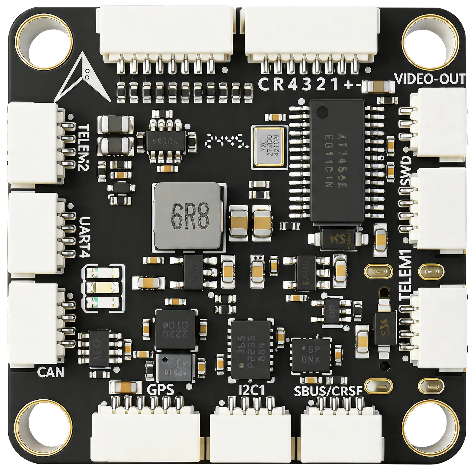
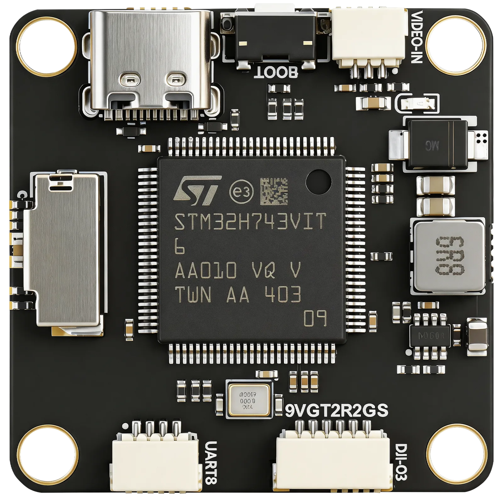
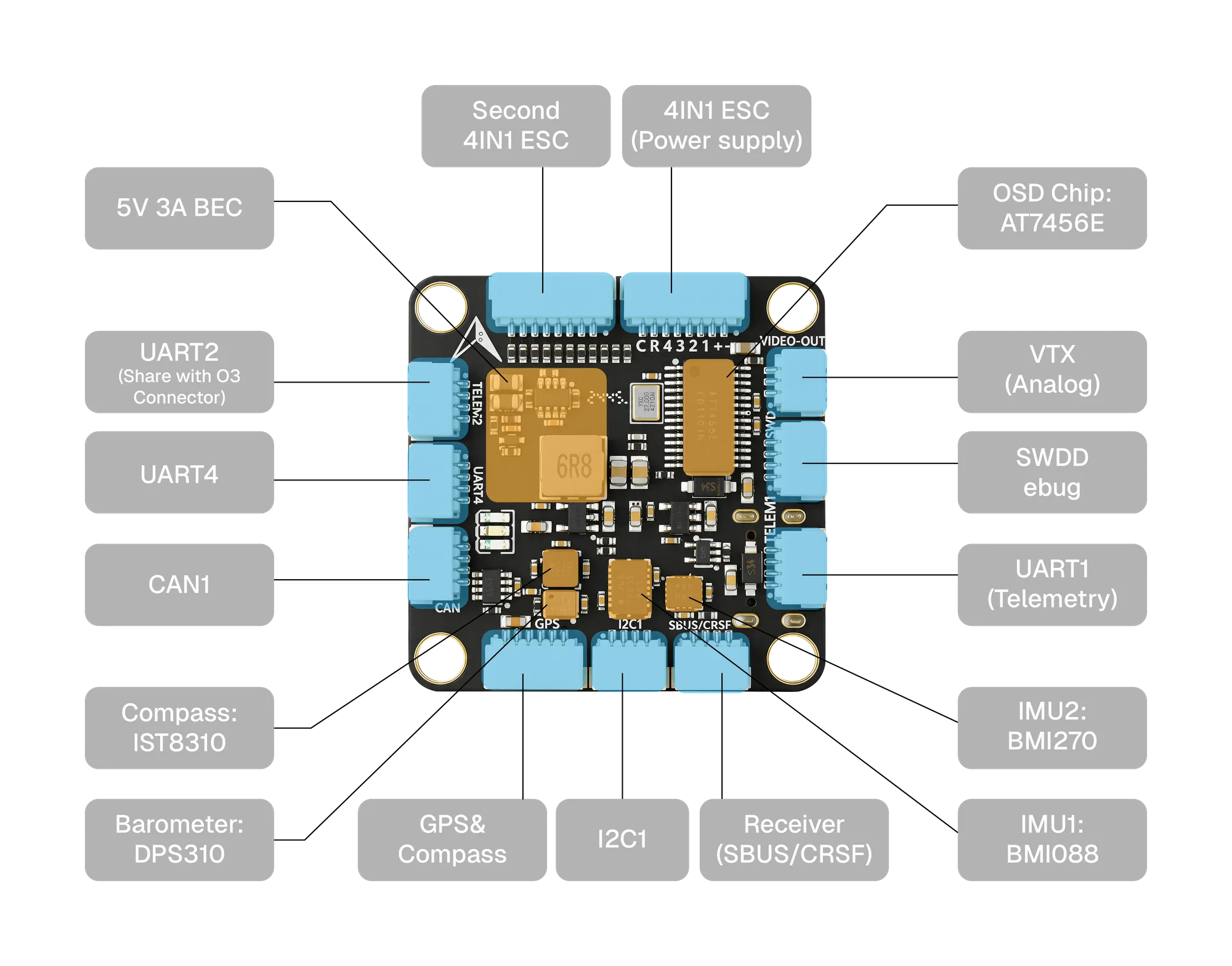
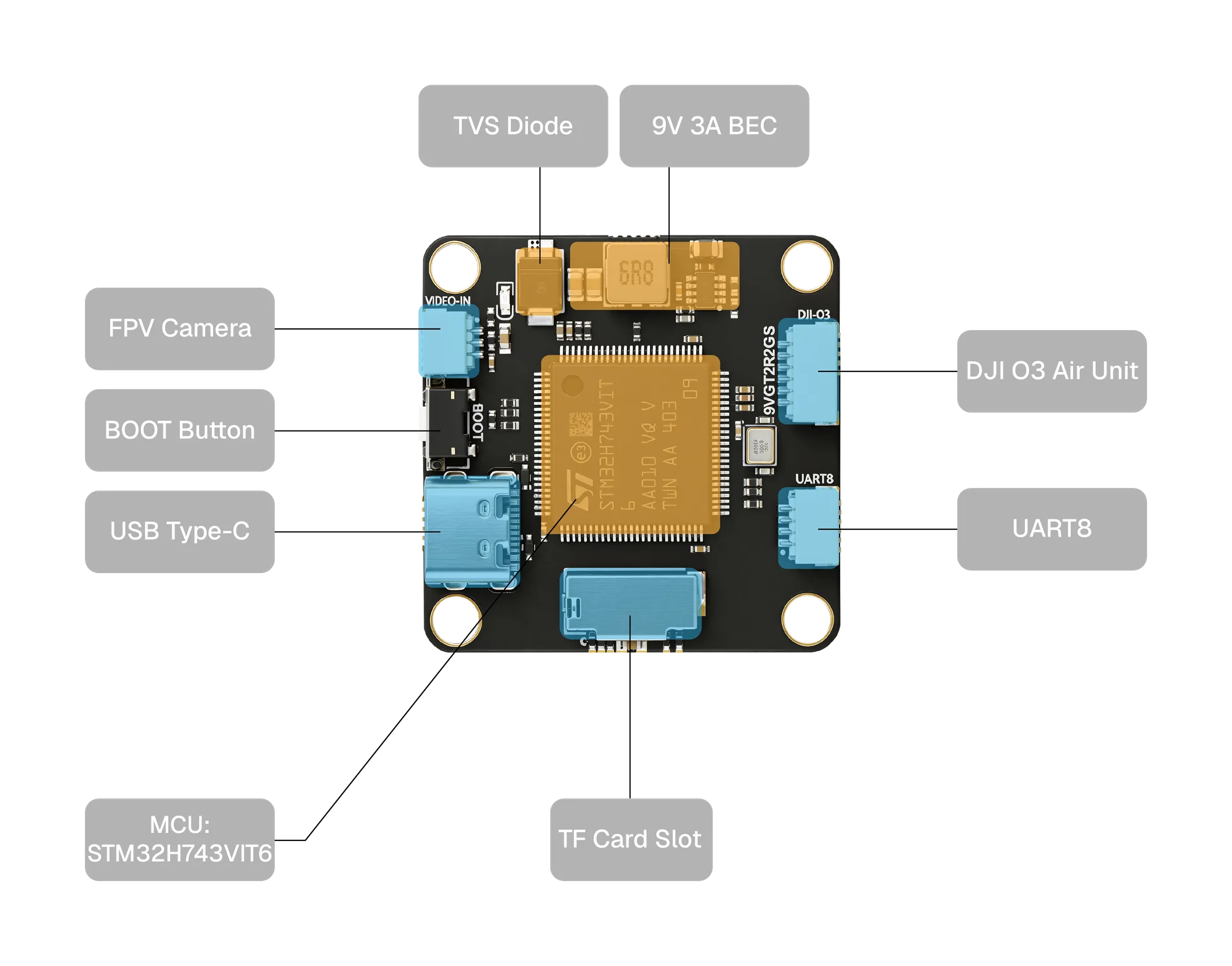
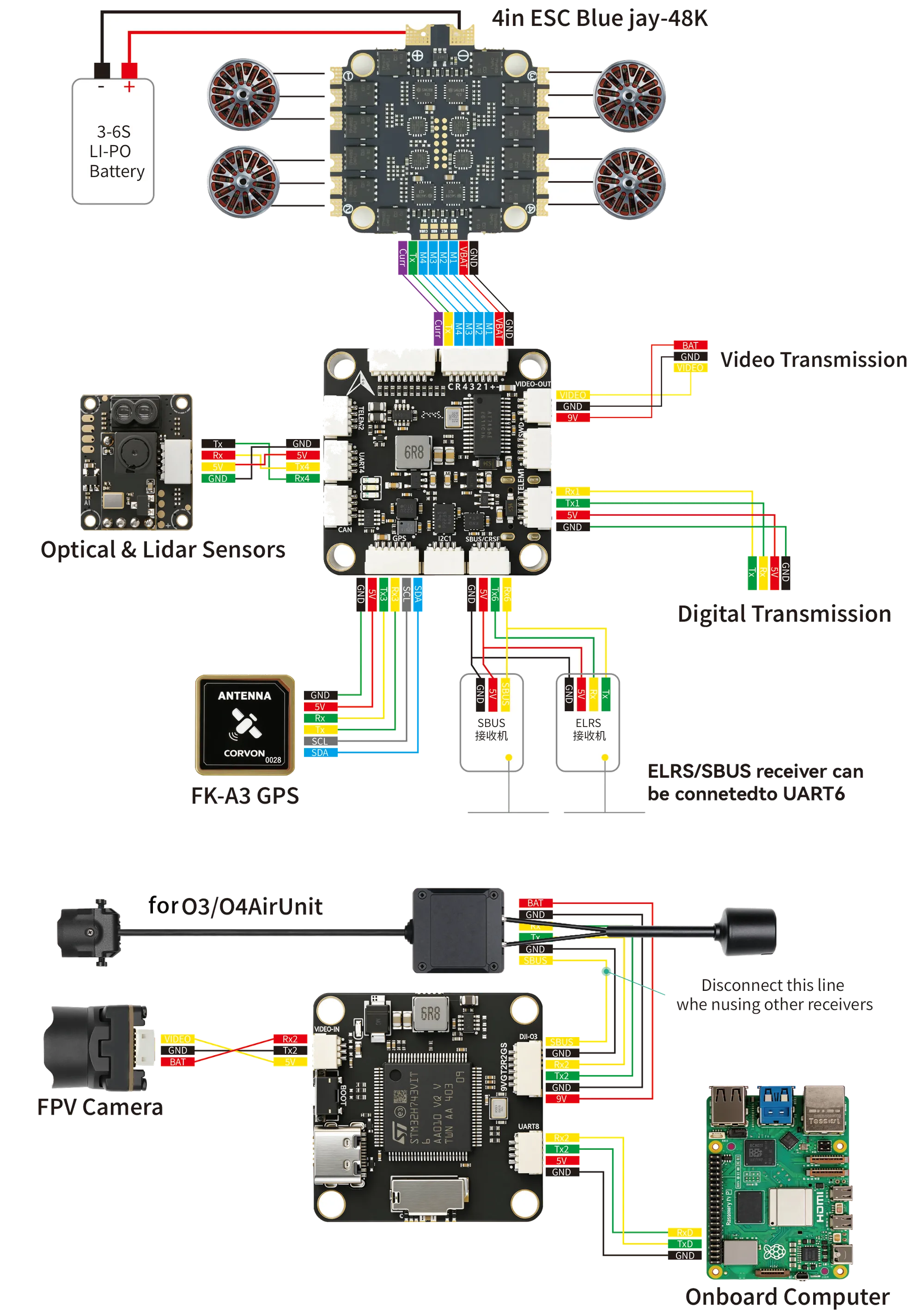
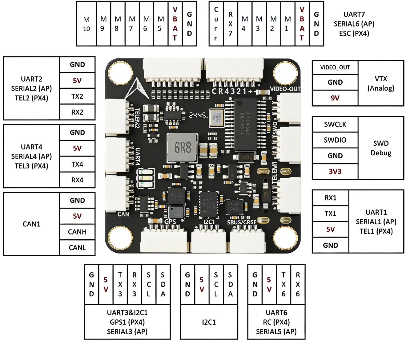
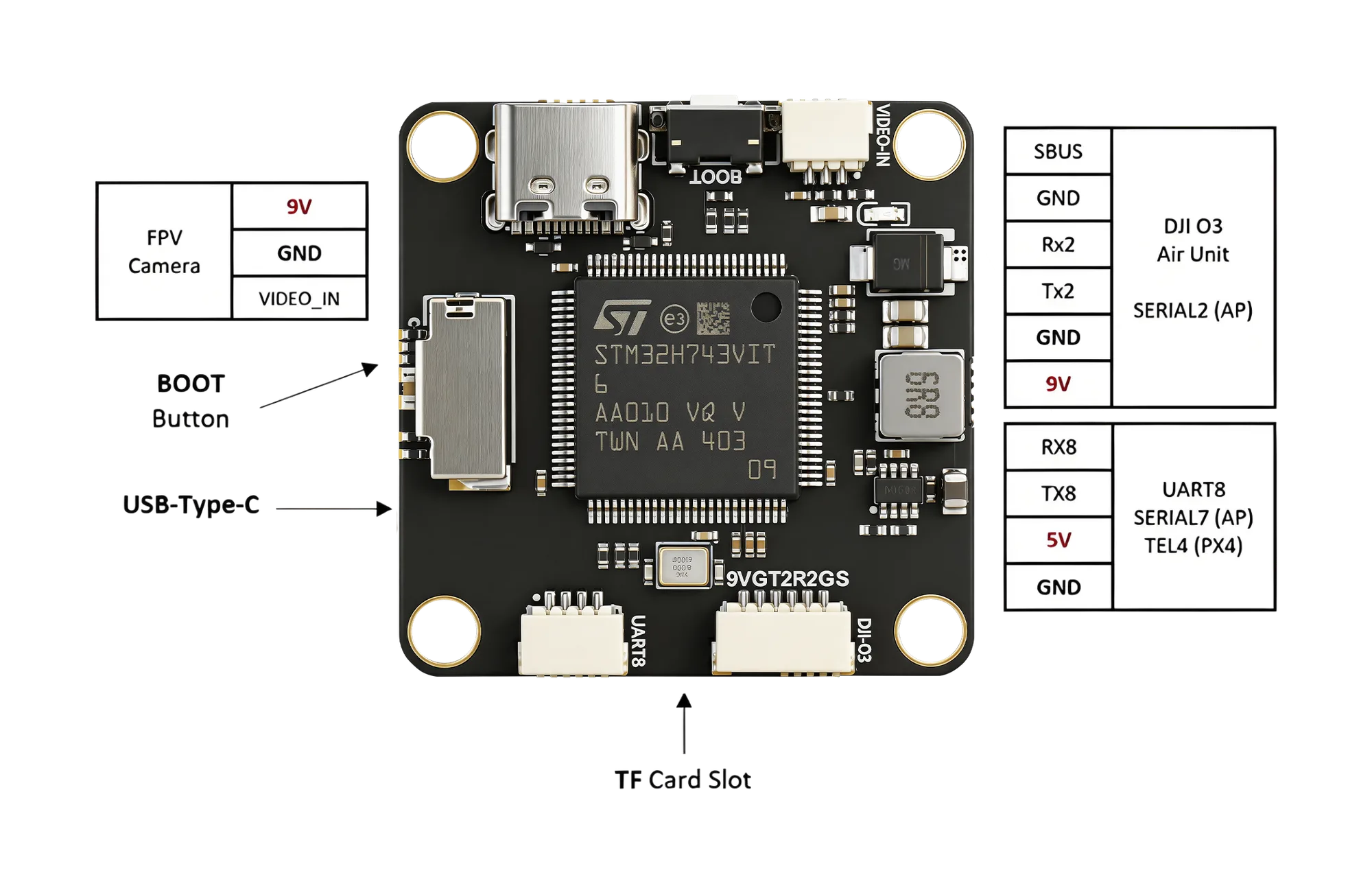
The CORVON 743v1 is a high-performance flight controller built on the STM32H743VIT6 Cortex-M7 MCU at 480 MHz. Dual IMUs (BMI088 + BMI270) pair with a DPS310 barometer and a built-in IST8310 magnetometer for precise navigation and stable flight. 7 UARTs and 10 PWM outputs, plus integrated AT7456E OSD, cover both hobbyist and professional UAV builds. Wide 2S–6S input with onboard 5V / 9.5V · 3A BEC. Compatible with the four major UAV firmware stacks — PX4, ArduPilot, INAV, and Betaflight.
| SKU | CORVON 743v1 |
|---|---|
| MCU | STM32H743VIT6 · Cortex-M7 · 480 MHz |
| Flash / RAM | 2 MB / 1 MB |
| Gyroscope | BMI088 / BMI270 |
| Accelerometer | BMI088 / BMI270 |
| Magnetometer | IST8310 |
| Barometer | DPS310 |
| OSD | AT7456E |
| BEC Output | 5V 3A · 9.5V 3A |
| Input Voltage | 2S–6S LiPo |
| UART | 7 |
| PWM | 10 |
| I²C | 1 |
| Operating Temp. | −40°C – 80°C |
| Weight | 9 g |
| Dimensions | 36 × 36 × 8 mm |
| Mounting Pattern | 30.5 × 30.5 mm · Φ4 mm |
| Firmware Support | INAV · ArduPilot · PX4 · Betaflight |
Thank you for choosing a CORVON product. Please read this disclaimer carefully — by using this product, you acknowledge and agree to the following: brushless power systems can be dangerous, and improper use may result in personal injury or equipment damage. Follow the installation and operation instructions carefully. Because we cannot control how this product is used, installed, or maintained, we accept no liability for any loss or damage arising from its use. Any unauthorized modifications are at your own risk.
Read this manual to understand all power configuration and flight parameters before powering the system. Installation requires soldering and wiring. Make sure all wires are properly insulated before connection to avoid short circuits. Use a soldering iron with adequate power to ensure solid joints — poor connections can cause loss of control or damage to your equipment.