The CORVON CV08 is a compact infrared ranging module built on the direct Time-of-Flight (dToF) principle for short-range distance measurement. It ranges from 20 mm to 8 m with a narrow <3° field of view, a measurement rate up to 50 Hz, and an eye-safe 940 nm light source. Its small 20 mm minimum spot and strong ambient-light immunity suit UAV altitude hold, robot and AGV obstacle avoidance, and proximity sensing in low-power systems. Distance is output over UART or I²C, making it a drop-in fit for PX4, INAV and ArduPilot. The module measures 13.0 × 16.0 × 9.25 mm and weighs about 0.6 g.
| Model | CV08 |
|---|---|
| Type | Infrared Ranging Module (dToF) |
| Measuring Range | 20–8000 mm |
| Field of View (FOV) | < 3° |
| Measuring Accuracy | ±3 cm @ <1 m · ±3% @ ≥1 m |
| Measurement Frequency | 1–50 Hz |
| Light Source Wavelength | 940 nm |
| Minimum Spot Size | 20 mm |
| Ambient Light Resistance | 8000 mm @ 350 lux · 4000 mm @ 100 klux |
| Operating Voltage | 3.5–5.5 V |
| Current Consumption | ≤ 20 mA @ 5 V |
| Communication Interface | UART 115200 · I²C up to 400 K |
| Operating Temp. | 0°C – 60°C |
| Storage Temp. | −20°C – 70°C |
| Dimensions | 13.0 × 16.0 × 9.25 mm (±0.1 mm) |
| Weight | 0.6 g |
| Firmware Support | PX4 · INAV · ArduPilot |
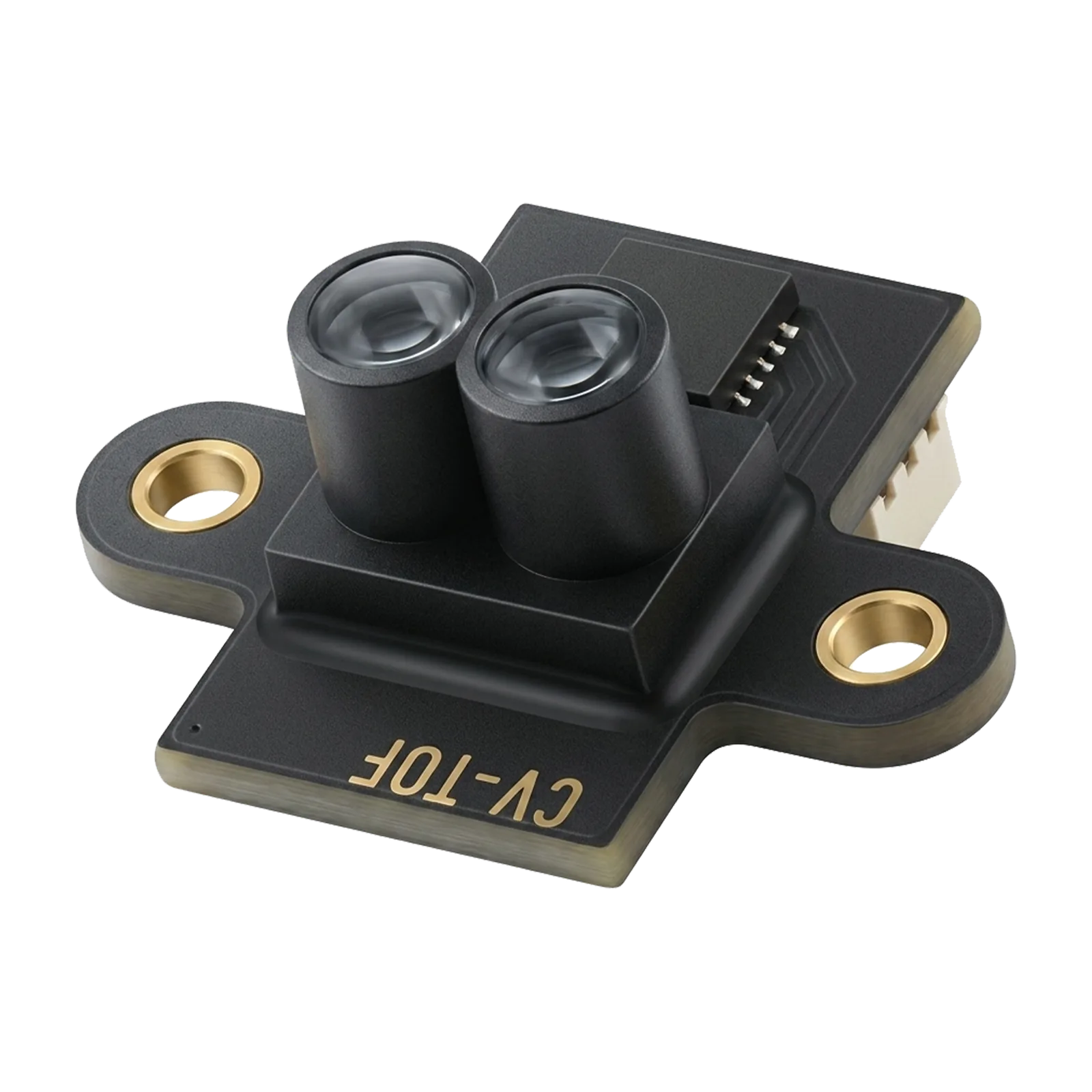
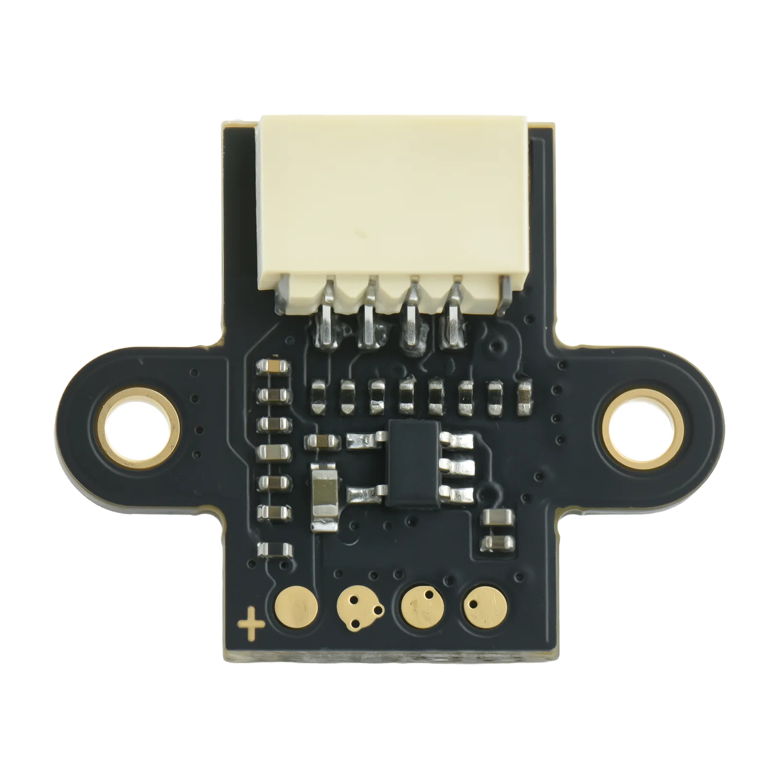
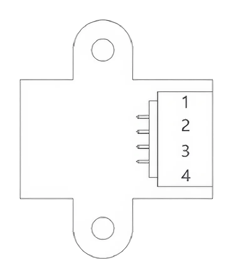
4-pin connector, UART / I²C selectable. For UART connect module TX to the flight-controller RX and module RX to the flight-controller TX (115200 bps).
| Pin | UART | I²C | Function |
|---|---|---|---|
| 1 | TX | SDA | UART transmit / I²C data |
| 2 | RX | SCL | UART receive / I²C clock |
| 3 | VCC | VCC | Power · +5 V |
| 4 | GND | GND | Ground |
UART Output Protocol
| S/N | Name | Content | Description |
|---|---|---|---|
| 1 | Header | 0xDF | |
| 2 | Device ID | 0x16 | |
| 3 | System ID | 0x00 | |
| 4 | Message ID | 0x55 | |
| 5 | Packet Sequence | 0x00~0xFF | |
| 6 | Payload Length | 0x04 | |
| 7 | Payload Content | TOF Dist Low Byte | TOF Distance (mm) |
| 8 | TOF Dist High Byte | TOF Distance (mm) | |
| 9 | TOF Signal Strength | 0~100 | |
| 10 | Reserved | Reserved for future use | |
| 11 | Checksum | 0xXX | Sum of all preceding bytes |
I2C Output Protocol(The I2C output protocol is proprietary and does not support open-source use.)
Device Address: 0x31 (7-bit)
| S/N | Register Address | Content | Description |
|---|---|---|---|
| 1 | 0x00 | Device ID | 0x16 |
| 2 | 0x01 | TOF Distance Low Byte | TOF Distance (mm) |
| 3 | 0x02 | TOF Distance High Byte | |
| 4 | 0x03 | TOF Signal Strength | 0~100 |
| 5 | 0x04 | Reserved | Reserved for future use |
PX4 Configuration
1. Open the tool and select Vehicle Configuration;

2. Set MAV_1_CONFIG to TELEM 2 and save;

3. Click “Tools,” then click “Reboot Vehicle”;

4. Set MAV_1_MODE to Normal and save;

5. Set SER_TEL2_BAUD to 115200 8N1 and save it;

6. Set EKF2_RNG_CTRL to Enabled and save.

7. Set EKF2_HGT_REF to Range sensor and save;

8. After the configuration is completed, restart the flight controller. You should be able to see the DISTANCE_SENSOR messages in the MAVLink Inspector page of QGC. It's fine as long as there is a change in the values. Note that the messages displayed on the QGC are sent by the flight control. The message frequency is not the same as the data frequency of the sensor. This frequency is determined by the Settings of the flight control and the speed of the data link, and is mainly used for observation. The number of the message frequency is not important.


II. APM Configuration
1. In Mission Planner, set the corresponding serial port baud rate SERIAL4_BAUD to 115(115200), the value SERIAL4_OPTIONS to 0, and set the serial port protocol value SERIAL4_PROTOCOL to 1(Mavlink1). Click "Write Params " to save;

2. Set the RNGFND1_TYPE value to 10 and save it;

3. Restart the flight controller, set the RNGFND1_MAX_CM value to 800, the RNGFND1_MIN_CM value to 1 and save them.

4. On the status page, you can see the values of rangefinder1.

III. INAV Configuration
1. Open the Ports interface, enable the MSP function for the corresponding serial port (we are connected to UART4), save, and restart.

2. In the Configuration interface, set the Rangefinder option and the Optical flow option to MSP, save and restart. If the configuration is correct, you can see that the Sonar indicator light and the Flow indicator light on the main interface are on.

3. On the Sensors screen, tick the Sonar option; if configured correctly, you should see the waveform and X-values changing:

Thank you for choosing a CORVON product. Please read this disclaimer carefully — by using this product you acknowledge and agree to the following. Because we cannot control how this product is installed, used, or maintained, we accept no liability for any loss or damage arising from its use, and any unauthorized modification is undertaken at your own risk.
Keep the optical window clean and unobstructed — dust, smudges, or a covering film will degrade ranging accuracy. Although the 940 nm source is eye-safe, do not stare into the lens at close range for extended periods. Mount the module rigidly with the lens facing the target surface, and observe correct wiring and polarity on the connector — reversed or mis-wired connections can permanently damage the module. Highly reflective, transparent, or strongly light-absorbing surfaces can affect readings; validate behavior in your environment before relying on it for flight.