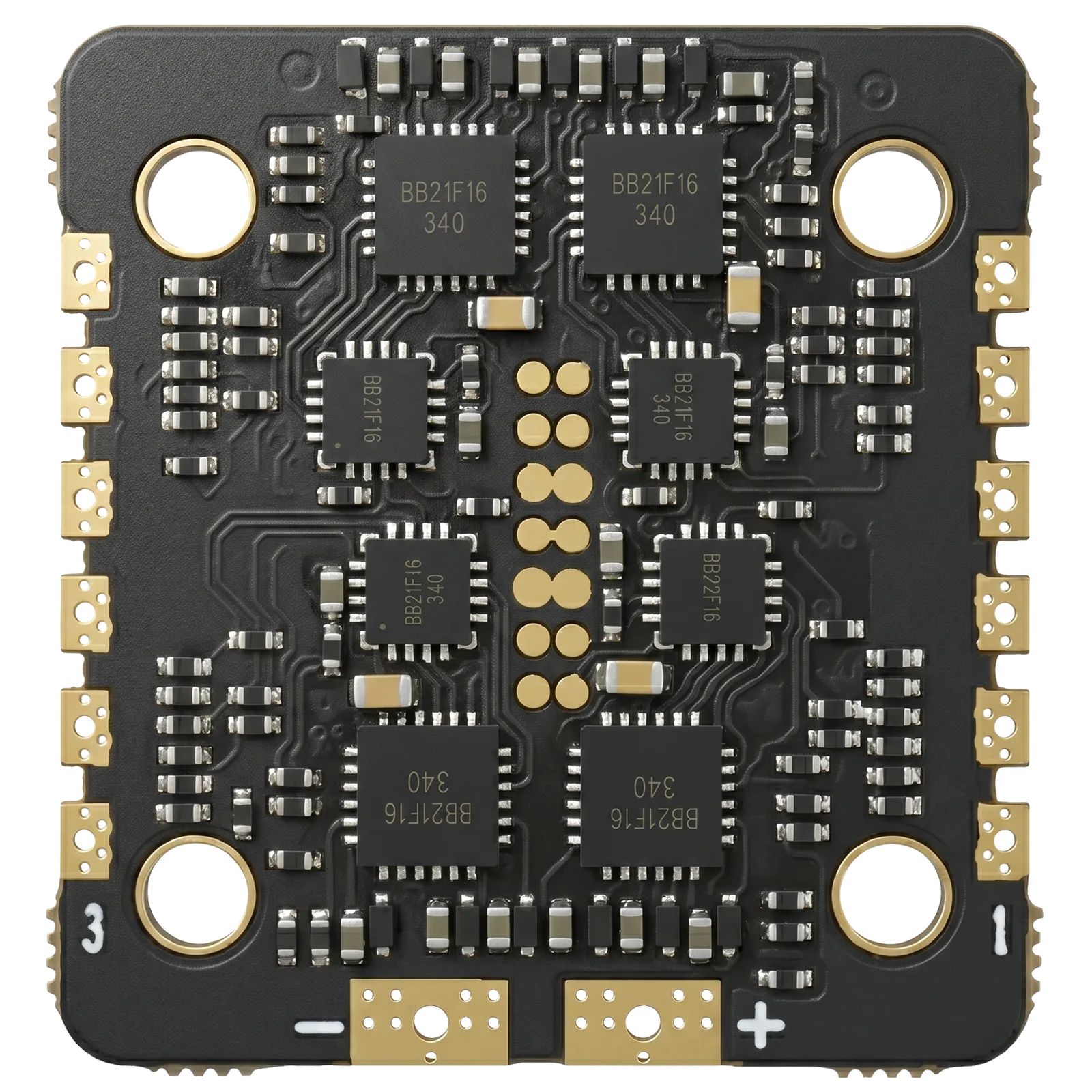
The CORVON 30A is a compact four-in-one brushless ESC driven by an 8-bit high-speed MCU, delivering 30 A continuous and 40 A burst (30 s) on each of its four channels across a 6–18 V (2S–4S) input range. High-frequency PWM with hardware synchronous rectification and regenerative braking gives excellent throttle linearity, faster deceleration, and higher battery energy-recovery efficiency. PWM, DShot, and OneShot drive protocols, a current-sense output, and onboard stall protection round out a power stage sized for sub-300 mm multirotors. The integrated 29 × 31 mm board mounts on a 20 × 20 mm M3 pattern, weighs roughly 5.6 g, and cools by natural convection.
| Model | 4in1-ESC-30A |
|---|---|
| Type | 4-in-1 Brushless ESC |
| Input Voltage | 6–18 V (2S–4S) |
| Continuous Current | 30 A × 4 |
| Burst Current | 40 A × 4 (30 s) |
| Drive Protocol | PWM · DShot · OneShot |
| MCU | 8-bit |
| BEC Output | None |
| Stall Protection | Yes |
| Cooling | Natural convection |
| Dimensions | 29 × 31 × 5 mm |
| Mounting | M3 × 4 · 20 × 20 mm |
| Weight | ≈ 5.6 g |
| Operating Temp. | −10°C – 55°C |
| HW / SW Version | 1 / 1 |
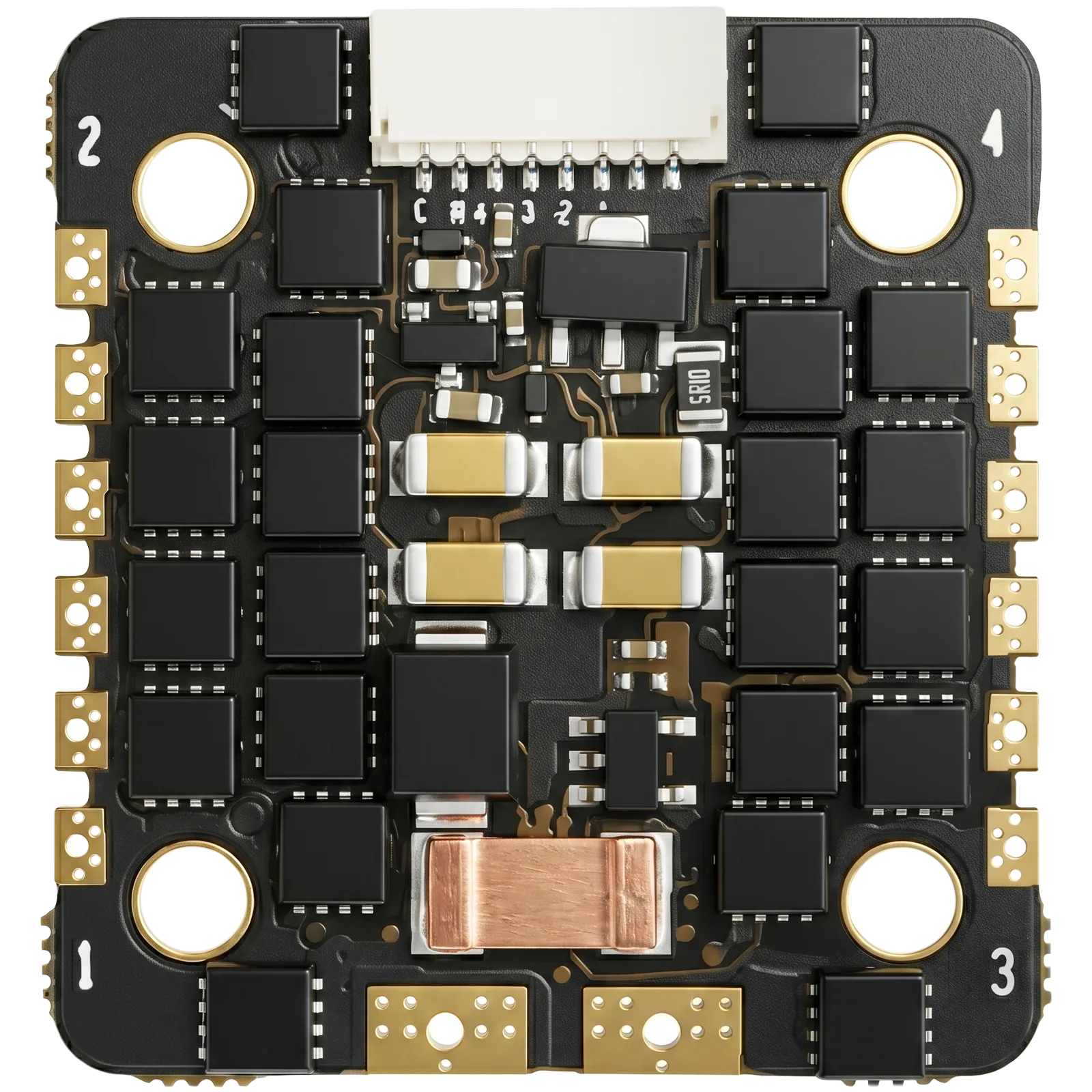
Signal-harness connector, pins ordered as silk-printed on the board (left to right). Observe polarity on the VBAT and GND pins.
| Connector | SH1.0-8P |
|---|---|
| Pin 1 · Curr | Current signal (ADC) |
| Pin 2 · NC | Not connected |
| Pin 3 · M4 | Motor 4 signal |
| Pin 4 · M3 | Motor 3 signal |
| Pin 5 · M2 | Motor 2 signal |
| Pin 6 · M1 | Motor 1 signal |
| Pin 7 · VBAT | Battery voltage |
| Pin 8 · GND | Ground |
Thank you for choosing a CORVON product. Please read this disclaimer carefully — by using this product, you acknowledge and agree to the following: brushless power systems can be dangerous, and improper use may result in personal injury or equipment damage. Follow the installation and operation instructions carefully. Because we cannot control how this product is used, installed, or maintained, we accept no liability for any loss or damage arising from its use. Any unauthorized modifications are at your own risk.
Read this manual to understand all power configuration and flight parameters before powering the system. Installation requires soldering and wiring. Make sure all wires are properly insulated before connection to avoid short circuits. Use a soldering iron with adequate power to ensure solid joints — poor connections can cause loss of control or damage to your equipment.