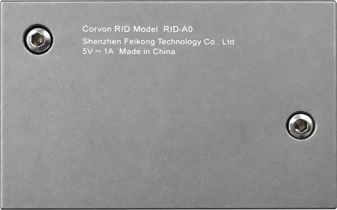
The CORVON RID is an add-on unmanned aircraft Remote ID broadcast module. It attaches to the airframe and connects to the flight controller with a single cable. The module obtains the aircraft's identification and position data from the flight controller and continuously broadcasts identification reports via Bluetooth, allowing any compliant receiving terminal, including a mobile app, to identify the aircraft in flight.
No flight-controller firmware or airframe modification is required: attach the module and connect one cable.
Document Information
| Version | V1.2 |
|---|
| Date | 2026-09-30 |
|---|
| Product Name | Civil Unmanned Aircraft Remote Identification Module (Remote ID Broadcast Module, add-on) |
|---|
| Responsible Manufacturer | Shenzhen Feikong Technology Co., Ltd. |
|---|
| Brand | CORVON |
|---|
| Model | CORVON RID (board model RID-A0) |
|---|
Product Features
- Add-on design: no change to the existing flight controller or airframe; installs with 3M adhesive and one GH1.25 cable to the flight controller.
- U.S. and EU modes on one hardware platform: the broadcast mode is preset at the factory for the variant you order.
- 11.2 g, 38 × 23.5 × 9 mm, CNC aluminum-alloy enclosure.
- Broadcasts at power-on: does not rely on a command from a ground station; broadcasting starts when powered.
- Configurable with a phone: built-in Wi-Fi configuration page opens in a browser; no dedicated software or driver is required.
- One-time identity lock: after locking, the identifier is read-only to prevent tampering.
- Signed OTA: online upgrade packages must carry a CORVON signature; writing is rejected if verification fails.
| Product Model | CORVON RID (board model RID-A0) |
|---|
| Main Processor | ESP32-C3 (RISC-V single-core, 160 MHz) |
|---|
| Memory | 4 MB Flash · 400 KB SRAM |
|---|
| Dimensions | 38 × 23.5 × 9 mm (module only, excluding antenna) |
|---|
| Weight | 11.2 g (including enclosure, excluding antenna) |
|---|
| Enclosure | CNC aluminum alloy |
|---|
| Mounting | 3M adhesive backing · no mounting holes |
|---|
| Power Supply | 5 V (via CAN / UART connector or USB-C) |
|---|
| Wireless Protocols | Bluetooth 5.0 (including Long Range / Coded PHY long-range broadcast) · Wi-Fi 802.11 b/g/n (configuration access point) |
|---|
| Operating Band | 2.4 GHz (2402-2480 MHz) |
|---|
| Broadcast Rate | Factory default: Bluetooth 5 Long Range at 2 Hz (once every 0.5 s) + Bluetooth 4 full message set at 1 Hz |
|---|
| Broadcast Start | Broadcasts at power-on; no ground-station command required |
|---|
| Antenna | External RID-ANT-01 · MMCX interface · 300 mm coaxial cable (included) |
|---|
| Compatible Flight Controllers | ArduPilot / PX4 · MAVLink over UART or DroneCAN over CAN |
|---|
| Interfaces | 2 × GH1.25 4-pin (CAN / UART) · USB-C (configuration) · MMCX (RF) |
|---|
| Configuration | Built-in Wi-Fi configuration page (browser) · USB-C console · web flashing tool at rid.corvon.tech (Chrome / Edge) |
|---|
| Firmware | Current version 1.33 · supports signed OTA online upgrades |
|---|
| Serial Number System | ANSI/CTA-2063-A · ICAO manufacturer code 2215 · laser marking · read-only after locking |
|---|
| Design Standards | ASTM F3411-22a / F3586-22 (U.S.) · EN 4709-002:2023 (EU) |
|---|
LAT 22.54°N · LON 114.05°E · SHENZHEN
| Interface | Pinout | Function |
|---|
| CAN (GH1.25 4-pin) | 1 = 5V · 2 = CAN-H · 3 = CAN-L · 4 = GND | Connects to the flight-controller CAN port (DroneCAN); pin order matches the DroneCAN standard JST-GH connector. |
| UART (GH1.25 4-pin) | 1 = 5V · 2 = RX · 3 = TX · 4 = GND | Connects to a flight-controller serial port (MAVLink); default 57600 bps. Pin 1 is the 5 V supply. Signals are 3.3 V TTL: connect directly to the flight-controller serial port; do not connect to a 5 V logic serial port. RX / TX are named from the module side: module TX to flight-controller RX, module RX to flight-controller TX. |
| USB-C | — | Configuration and firmware flashing; driver-free. |
| MMCX | — | RF output; connects to external antenna RID-ANT-01. |
| Variant | Transport | Broadcast Content |
|---|
| US | Bluetooth 4 + Bluetooth 5 Long Range | ASTM F3411 Remote ID message set |
| EU | Bluetooth 4 + Bluetooth 5 Long Range | Remote ID message set + EN 4709-002 operator registration number |
Both variants use the same hardware; the broadcast mode is preset at the factory for the variant ordered.
The antenna is external, and its installation location directly determines whether ground reception is possible. Follow all three requirements:
- Install the antenna vertically, with the long edge of the antenna board upright.
- Mount it on a non-metallic, non-carbon-fiber surface.
- Keep metal and carbon fiber at least 10 mm away from the back of the antenna.
For a carbon-fiber airframe, route the antenna to a non-carbon-fiber location, such as the landing-gear cover or an antenna bracket, before attaching it.
| LED Pattern | Meaning |
|---|
| Rapid red → green → blue sequence at power-on | LED self-test (once) |
| Dim white breathing | Booting (approximately the first 15 s) |
| Blue double flash (twice every 2 s) | No flight-controller data received. Check the cable and flight-controller serial-port settings. |
| Cyan breathing | Connected to the flight controller and waiting for a GPS fix (normal indoors). |
| Yellow breathing | Operating normally; identity not locked. |
| Green breathing | Operating normally; identity locked. |
| White flash at 1 Hz | Firmware upgrade in progress; do not power off. |
| Red triple flash | Fault. Power cycle once; if the red indication remains, contact after-sales service. |
| Item | Description |
|---|
| RID-A0 module × 1 | The bottom label is printed with the module serial number and the onboard Wi-Fi configuration password, unique to each unit. |
| Connection cable × 2 | One CAN cable and one UART cable. |
| External antenna RID-ANT-01 × 1 | Includes a 300 mm coaxial cable and straight MMCX male connector. |