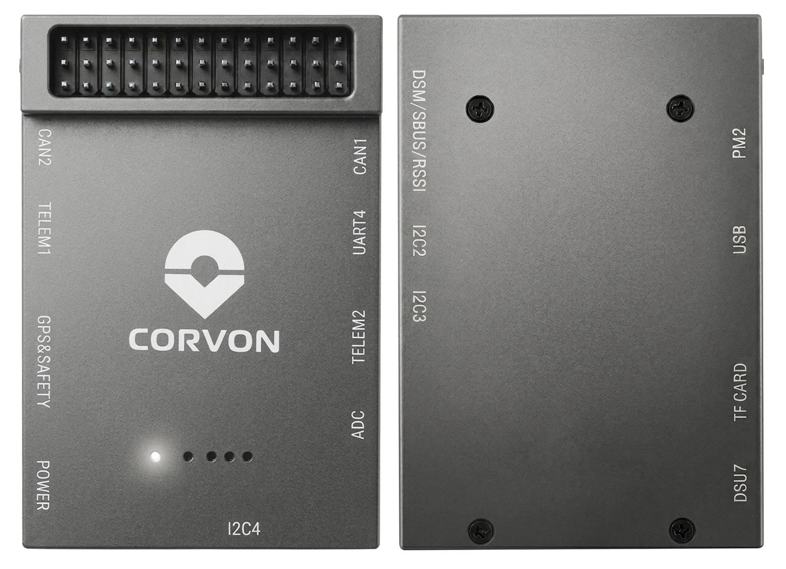
CORVON V5 is a high-performance flight controller designed for UAV systems, especially industrial aircraft applications, and is compatible with ground-control and firmware ecosystems such as ArduPilot and PX4. Built around the STM32F765IIK6 MCU, it integrates multiple IMU sensors, an onboard compass, and a barometer to support stable attitude estimation, navigation, and flight control. The enclosed plug-in connector design provides 5 UART, 11 PWM outputs in ArduPilot, 2 I²C, dual CAN, power-module ports, receiver ports, debug access, and a TF card slot for professional UAV and multi-peripheral system integration.
| MCU | STM32F765IIK6, 216 MHz |
|---|---|
| RAM | Total 512 KB: DTCM RAM: 128 KB (tightly coupled memory, low latency); AXI SRAM: 256 KB (high-speed bus); SRAM1/2/3: 128 KB (general purpose) |
| Flash | 2048KB |
| Gyroscope | BMI088 / ICM-20602 / ICM-20689 |
| Accelerometer | BMI088 / ICM-20602 / ICM-20689 |
| Onboard Compass | IST8310 |
| Barometer | MS561101BA03-50 |
| Operating Temperature | -40°C - 80°C |
| UART | 5 |
| PWM | ArduPilot: 11 outputs (8 main M1–M8 + 3 auxiliary A1–A3). The nARMED pin is not a PWM output. |
| I2C | 2 |
| Firmware Support | Ardupilot/PX4 |
| BEC Output | None |
| Recommended Operating Voltage | PW1: 4.8V-5.5V; PW2: 12V-36V (supports high-voltage input for multiple power systems) |
| Voltage Sampling Ratio | According to the current-meter standard on the matched ESC current meter |
| Weight | 40.5g |
| Dimensions | 61.2mm*40mm*15.92mm |
.webp)
.webp)
Thank you for choosing a CORVON product. Please read this disclaimer carefully: by using this product, you acknowledge and agree to the following terms. Brushless power systems involve potential hazards, and improper use may cause personal injury or equipment damage. Always follow the installation and operating instructions. Because we cannot control how this product is used, installed, or maintained, we assume no responsibility for any loss or damage arising from its use. Any unauthorized modification is performed at your own risk.
Before powering the system, read this manual and understand all power configurations and flight parameters. Installation may require soldering and wiring. Make sure all wires are properly insulated before connection to avoid short circuits. Use a soldering iron with suitable power to ensure solid joints; poor connections may cause loss of control or equipment damage.